- CFD, Fluid Flow, FEA, Heat/Mass Transfer
CFX / FLUENT Troubleshooting
Error / Warning messages in ANSYS FLUENT and CFX
[Q] I am comparing CFX result with FLUENT result. However, my 1st check after getting a converged solution is unexpected: Y+ value reported by CFX is far off than that reported in FLUENT!
[A] If your B.C. and material properties are identical, both the results would be true within error limits. However, the difference arises due to the "Staggered" Vs. "Collocated" algorithm used in FLUENT and CFX respectively. Due to the staggered approach used in FLUENT, the 1st cell height near wall used for Y+ calculation is half of the mesh height you set in mesher. However, in CFX, it is evaluated at the node of the 1st layer. Hence, if same mesh is used, the Y+ value reported in CFX should be ~ 2-times the value reported in FLUENT.
[Q]I am using conformal mesh on the two faces of a periodic B.C. However, mesh connection option available in CFX is still GGI and not 1:1. My understanding is that GGI option is used only for non-conformal interfaces.
[A] When each face of an interface do not have one co-ordinate identical, CFX uses GGI. Since, the X-, Y-, Z-coordinates of the two faces will be difference, CFX uses GGI option only.
[Q] What are sample 'SCHEME' files for automation in ANSYS FLUENT?
[A]Ref: https://www.cfd-online.com/Forums/fluent-udf/81520-journal-fluent-scheme-programming.html
(Do ((u 0.0 (+ u 0.1))) ((> u 1.0))
(Ti-menu-load-string (format #f "surface/iso-surface z-coordinate z-plane-~a () () ~a" u u)) )
Here 'u' is a local variable that stores values 0.0, 0.1, 0.2 ... 1.0. The above scheme creates iso-surfaces from z = 0.0 to z = 1.0 at an interval of 0.1 and assigns name of the planes as 'z-plane-0.1', 'z plane-0.2'... "~a" stands for a random variable tilde (~) controls a pattern, like %-character in C language.
- '~a' random variable in general format (string without double quotes "")
- ~ d: integer number
- ~04d: integer with zeros on the front is always 4 digits fill ( 5 is about 0005), eg this is important for file names
- ~f: floating-point number
- ~4.2f: floating point number, a total of 4 characters long, 2 digits after the decimal: 1.2 will be 1.20
(do ((x 0 (+ x 0.2)) (i 1 (+ i 1))) ((> x 3.1))
 (ti-menu-load-string (format # f "surface / iso-surface x-coordinate ~ x-02d () ~ a () 'ix))
)
This will generate the following text interface (TUI) commands:
surface / iso-surface x-coordinate x-01 () 0.0 ()
surface / iso-surface x-coordinate x-02 () 0.2 ()surface / iso-surface x-coordinate x-03 () 0.4 ()
.. .surface / iso-surface x-coordinate x-16 () 3.0 ()
[Q] How do I export the name of the zones and type of boundary conditions assigned to them?
[A]: FLUENT assigned a unique ID to each face and cell zones. However, UDF cannot access the zone names. Following scheme command will print the list in FLUENT console. Note '~a' is a random variable. Comment starts with ;; and ends with a newline character.(define (export-bc-names)
(for-each
(lambda (name)
(display
(format #f " {~a, \"~a\", \"~a\"},\n"
(zone-name->id name) name (zone-type (get-zone name))
)
)
) (inquire-zone-names)
)
)
[Q] There are two types of residual option available in CFX: RMS and MAX. Which one should I use to set convergence criteria and why?
[A] For a well-posed problem, both the RMS and MAX norms behave identically and differ by an order of magnitude. However, in cases where there is strong swirl or separation-reattachment, the MAX norm will be far higher than RMS norm. Hence, it is acceptable to set RMS residual as the Convergence Criteria where the magnitude of limit [1.0E-4 or 1.0E-5 or 1.0E-6] may be selected based on problem specific experience.[Q] I am studying the effect of various operating conditions on a given geometry and similar but different type of mesh. How do I ensure that the Solver Setting, Material, Discretization Scheme remains same for all such cases?
[A] Export the B.C. and other setting information as CCL format from 1st file and import is into another file.
[Q] I want to estimate heat flux on a portion of wall for a given temperature limits. The temperature is varying asymptotically. How do I accomplish it without going back to mesher to split the wall based on results which I have already obtained?
[A] Adjust the contour setting [range of temperature and number of colours] so that it intersects with the temperature bounds you are interested in. Then you can make user surfaces for each level of the contour. Use the user surfaces falling under temperature bounds of your choice.
[Q] Does CFX has a database where common Fluid properties as a function of temperature can be set for ideal gases such as Air, H2 and most common fluid Water?
[A] No. You need to write CEL Expression for this. For common fluids like mentioned here, the information is readily available in Standard Textbooks on Fluid Flow. One example for air is given below:
CpAir = 1030.33 [J/kg/K] - 0.196044 [J kg^-1 K^-2] * T + 3.93365E-4 [J kg^-1 K^-3] * T * T
kAir = 6.24978E-6 [W m^-1 K^-1] + 9.73517E-5 [W m^-1 K^-2] * T - 3.31177E-8 [W m^-1 K^-3] * T * T
muAir = 1.458E-6 [Pa s K^-0.5] * T^1.5 / (110.4 [K] + T)
Here, T is in [K], the default unit of Temperature used by Solver.
[Q] I have prepared a mesh and obtained solution for 3 operating conditions and 2 turbulence models. Thus, simulation set will consist of 1 [mesh] x 3 [B.C.] x 2 [Turb. Models] = 6 case files. I want to do sensitivity analysis by repeating the same task for 2 more mesh refinements. Can this process be automated i.e. the script reads new mesh files, imports B.C. setting from old cases, starts solver and prepares result file?
[A] Yes. This is very much possible which requires a beginner's level knowledge of PERL and CFX Pre CCL. A sample script for this particular purpose is given below:
COMMAND FILE:
  CFX Pre Version = 12.1
END
# /usw/cfx12.SP1.0_0/v121/CFX/bin/cfx5pre -batch BatchCFX.pre
# Create an ARRAY which holds names of the Mesh Files
# It is assumed that the mesh format is *.cfx5
! @MeshFiles = (MeshData1, MeshData2, MeshData3, MeshData4);
! @FilesCCL = (FilesCCL1, FilesCCL2, FilesCCL3, FilesCCL4);
! @FilesDef = (FilesDef1, FilesDef2, FilesDef3, FilesDef4);
! @FilesCFX = (FilesCFX1, FilesCFX2, FilesCFX3, FilesCFX4);
! $LEN_msh = @MeshFiles;
! $LEN_CCL = @FilesCCL;
! $LEN_Def = @FilesDef;
! $LEN_CFX = @FilesCFX;

#--------------------------------------------------------------------
! for ($i=0;$i<$LEN_CFX;$i++) {
# Use this section when EXISTING *.cfx files are to be opened
>load filename=/home/userX/Case07.cfx, mode=cfx, overwrite=yes
> update

# -------------------------------------------------------------------
# Use this section only when MESH data needs to be imported
#>load mode=new
#> update
#! $temp = "/home/userX/" . $MeshData[$i] . ".cfx5";
#>gtmImport filename=/home/userX/MeshData.cfx5, \
#type=Generic, genOpt= -n, units=mm, nameStrategy= Assembly
#> update
#--------------------------------------------------------------------

>importccl filename=/home/userX/Test_CCL.ccl, mode = replace, \
autoLoadLibrary = none
> update

! $temp = "/home/userX/" . $FilesCFX[$i] . ".cfx";
>writeCaseFile filename=$temp
> update

! $temp = "/home/userX/" . $FilesDef[$i] . ".def";
>writeCaseFile filename=$temp, operation=write def file
> update

#----------------Save CFX File --------------------------------------
>writeCaseFile
> update
#---------------Close CFX File --------------------------------------
>close, deleteLibrary = On
> update
!}
[Q]How to stop a CFX solution run before assigned number of iterations while saving the latest results!
[A]: For Linux & Windows: one way is to edit the run using solve console by changing the number of iterations to the next value of ongoing iteration. Alternatively, cfx5stop command can be used.
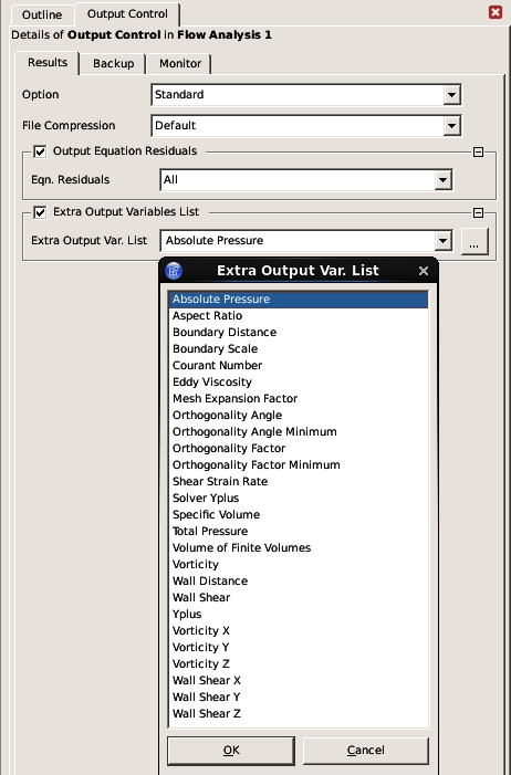
[Q]I am not able to plot equation residuals during post-processing!
[A]: You need to switch-on the "Output Equation Residuals" tab as shown below:
[Q] I have created a 2D mesh in ICEM CFD using blocking. However, FLUENT is unable to read the data and prints error message "Segementation Violation"!
[A] Before I answer to your question, be informed that "Segmentation Violation" message is not unique to a particular error. There may be many causes to your problems. Follow the following steps to trace them:
- Check the ICEM translation log in its message window. Was the translation clean? If not, rectify them and recheck. If yes, read next point.
- Have you selected the correct option "2D" for 2D mesh?
- Run the utility "Check Mesh" under "Edit Mesh" tab and rectify error messages, if any. Warning messages can be ignored most of the time, do check them and rectify as far as possible.
[Q]If have change the material from "Air" to "Water" using GUI: Define > Material. However, the solver is still using Air.
[A] In most of the cases, the user has to manually set the material for the domain ("fluid" boundary condition) to new material defined.
[Q] I have created a 3D axi-symmetric mesh in ICEM CFD. There was NO error message during "Mesh Check" in ICEM. The mesh on the periodic faces are conformal i.e. 1:1. However, grid check in FLUENT is not printing correct value of periodicity.
[A] It requires a small adjustment in FLUENT. You have to use TUI: define > boundary-conditions > repair-periodic. Sometimes, creation fails because of slightly non-matching mesh nodes, increasing the matching tolerance up to 0.5 (default is 0.05) may help: grid/modify-zones/match-tolerance.
[Q] I am studying the effect of various operating conditions on a given geometry and similar but different type of mesh. How do I ensure that the Solver Setting, Material, Discretization Scheme remains same for all such cases?
[A] There are two ways you can accomplish this:
- Write or record a [clean] script [FLUENT Journal] for 1st set of simulation. Change only those variables which you want to change. Read it in subsequent case files.
- Once the Case file is set as per your requirements, use TUI "File -> write-BC" to write all the settings to a file. Read it after mesh import in later cases. Change B.C. such as mass flow rate, temperature, etc manually.
[Q] When I import a mesh created in ICEM CFD V12.1, I get following error message:
 Warning: Thread 62 has 8 contiguous regions.
        creating extn_int1-shadow
        creating extn_int2-shadow
What is the error about and how do I rectify it?
[A]: Note that this is a "Warning" message and not an "Error" message. This message appears usually when there is common edge sharing two different zones of same type (say type "Fluid" on both sides). In this case, you need to go to Define > Boundary Condition and set the extn_int1 & extn_int2 as "Interior".
[Q] I have prepared a 2D mesh in ICEM CFD V12.1. The "Mesh Check" under "Edit Mesh" tab reports no error message. When I tried to import this mesh in FLUENT V6.3.27, following error message was reported:
WARNING: Unassigned interface zone detected for interface 56
WARNING: Unassigned interface zone detected for interface 57
Checking storage.
[A] One of the case observed is when there is an internal edge and the the two surface mesh either side are in same "part". Sometimes, particularly in ICEM V12.1, if any part name is named as interface_*****, they are automatically assigned the boundary condition type "INTERFACE" in FLUENT. The remedy is either to remove "interface" from name of the part or create a "grid interface" in FLUENT involving zone ID 56 & 57. The former is recommended action.
[Q] While creating a "grid interface", following error message is reported:
Error: Zone interface_bot already in another interface
Error Object: #f
[A]: This message is generated when a particular "interface zone" is being used in more than 1 "grid interface". This is an error message just to remind you that you are attempting to make an unrealistic interface and FLUENT would not have allowed you to do so anyway.
[Q] When I created a JPEG file of contour plot, some portion of legend is missing
[A]: You need to adjust the size of the window (top-right corner of the "Save Hardcopy" pop-up window).
[Q] How do I start FLUENT in batch mode?
[A]: The method varies depending upon operating system (OS).- For windows, to start FLUENT in 3D mode, use "fluent 3d -g -i batch.jou -hidden". Note that without command line option '-hidden', the GUI will still be started but show as an icon. Replace '3d' by '2d' to start fluent in 2-dimensional mode.
- In Windows, a transcript file cannot be generated through command line. It should be (can be) started and stopped withing FLUENT session.
- For Linux or Unix environment, the method further depends on shell:
- For C-shell: fluent 3d -g < Input.jou >& Output.trn &, where Input.jou is journal script to make fluent read all the necessary files and commands and Output.trn is the transcript file which it will write.
- For Bash (Bourne Shell) and ksh (Korn Shell): fluent 3d -g < Input.jou > Output.trn 2>&1 &
- Note that the ampersand (&) at the end of the command tells the OS not to wait till completion of the execution of that line. This is also called running the command in background.
- Note the following additional requirement of run FLUENT in batch mode:
- "Confirm file overwrite" should be set to 'Yes' for all batch processing. This is to avoid the user prompt to over-write the case file when save frequency is set.
- Alternatively, "Hide Questions" and "Exit on Error" can be switched on and let FLUENT handle itself
- Incidentally, all these 3 settings can only be done through GUI and no equivalent script or TUI command is available. Hence, Scheme command, for example (set! *cx-exit-on-error* #t) to switch on "Exit on Error" option, needs to be used.
[Q] We have limited FLUENT solver license and try to minimize its utilization. For this purpose, we try to start next runs as soon as possible (the solution does not take more that an hour and needs to simulate around 100 cases). Is there a way to keep solver busy all the time?
[A] This can easily be done by starting solver in batch mode. You can prepare many case and data file using FLUENT Post and use following input files to keep solver running all the day-and-night:
You need to run FLUENT in batch mode and specify following content as Input.jou. Note that the file extension does not need to be .jou. Instead it can be .in as well.
For Linux:
-------------------Input File Starts------------------
file/read-case-data Case01.cas
solve/iterate 5000
file/confirm-overwrite no
file/write-data Case01.dat
file/read-case-data Case02.cas
solve/iterate 5000
file/confirm-overwrite no
file/write-data Case02.dat
file/read-case-data Case03.cas
solve/iterate 5000
file/confirm-overwrite no
file/write-data Case03.dat
... so on
For Windows: Create a batch file with following content
call cd .\Case1
call fluent 3d -wait -g -i Case1.jou
call cd ..\Case2
call fluent 3d -wait -g -i Case2.jou
-------------------Input File Ends------------------
[Q] Warning: FLUENT continuously reports the warning message for exceeding the limit of turbulent viscosity ratio.
[A]: This message is an indication of TVR exceeding the default limit of 1.0E+5. The primary cause for such an unphysical value may be: Poor mesh quality (i.e., skewness > 0.85 for Quad/Hex, skewness > 0.90 for Tri/Tetrahedral elements), Use of improper turbulent boundary conditions, Not supplying good initial values for turbulence parameters.
[Q]I try to define operating pressure at a point in FLUENT. The co-ordinates have been taken from mesh model in ICEM where size of the domain was in mm say (X0, Y0, Z0). FLUENT gives warning message: "The point is outside the domain"!
[A]: Note that all the solvers converted the input "length" dimensions into meter by scaling up/down the input mesh model appropriately. Since, the scaling is usually done about origin of centre of the volume (in 3D) / area (in 2D), the location of point being considered may not be (X0/1000, Y0/1000, Z0/1000). It is always better to find the co-ordinate by mouse-probe function.
[Q]How to stop a fluent solution run before assigned number of iterations while saving the latest results!
[A]: For Linux:
- to save and exit, create an empty file named "stop-fluent" in /tmp folder. It will make a "#restart.inp" file in the directory from which batch run was started. The files will be written to the same directory where the original input files were read and will have the same names but with appended current iteration number. By default, the case file will be written
- If the machine has several FLUENT sessions running, named check pointing can be used selectively. To stop this particular job, use the following command inside the /tmp directory: "touch exit-fluent-job-1"
- To check your job (i.e. to save data for latest iteration and continue the run) create a file named "check-fluent" in your /tmp directory. Check-pointing code calls the same file I/O routines used by the GUI or TUI and will produce the same error messages if disk space is insufficient In such case, FLUENT will not return to the iteration loop.
- To write data file only, execute following Scheme command before iterating: (rpsetvar 'checkpoint/write-case? #f)
- If the machine has several FLUENT sessions running, named check pointing can be used to selectively stop a specific FLUENT process. A specific check point name can be added to the first line of the batch journal file, as shown below:
(set! checkpoint/exit-filename "/tmp/exit-fluent-job-1")
file/read-case-data sample.cas
solve/iterate 1000
file/write-case-data final.cas
- to save and exit, create an empty file C:\temp\exit-fluent.txt
[Q] Can I read a journal file from another file?
[A]: The answer is 'No'. Note that scripting is not a full-fledged programming language and nesting is not allowed.[Q] Why the direction of rotation I specify in FLUENT is not matching with what I intended for?
[A]: "Right hand rule" needs to be followed to specify the value of Rotation Angle. E.g. if axis of rotation is along positive X-axis and direction of rotation is from Y-axis towards Z-axis, the angle of rotation would be positive.[Q] I make runs on remote machines which take long time. How do I get to know that run is finished without continuous monitoring?
[A]: The runs are normally made on remote machine in batch mode using an input file described earlier. FLUENT can notify the user by e-mail after the completion of a batch job if following line at the end of the batch journal (used to start the run) is added: !mail [e-mail address] < [body.txt] where [e-mail address] (without square brackets) is the user's e-mail address and [body.txt] (without square brackets) is the file, located in the directory where case and data files are stored, that contains the message to be sent.[Q] I am unable to generate ANIMATIONS in FLUENT in batch mode?
[A]: Following option need to be added during start up command of the batch job: -driver null[Q] How do I customize FLUENT during start up, for example changing the default setting to k-ε instead of laminar, FPS unit system instead of SI, convergence norm to 0.00001 instead of 0.001 and so on?
[A]:- Almost all the programs use a "start-up" file and FLUENT is no exception. It auto executed a .fluent file in "home directory" of Linux/UNIX users and C:\ drive of Windows users.
- This file contains Scheme commands to execute as well as it can contain other files containing Scheme commands to load
- As per the the standard norm of any operating system and programming language, FLUENT will search to locate the Scheme files from the working directory unless full path is specified for each Scheme file in .fluent file.
- Example is:
(set! *cx-exit-on-error* #f)
;turn OFF exit-on-error
(let ((menu (cx-add-menu "USC" #\U)))
(load mysettings.scm)
(load postproc.scm)
[Q] Error: Invalid section id: Error Object: #f
Some of the likely causes are (a) a change in case file such as faces were split or merged or renamed... (b) you have dynamic mesh and the mesh is different, (c) data file was saved, but not the case file - and hence case and data files don't match.The content on CFDyna.com is being constantly refined and improvised with on-the-job experience, testing, and training. Examples might be simplified to improve insight into the physics and basic understanding. Linked pages, articles, references, and examples are constantly reviewed to reduce errors, but we cannot warrant full correctness of all content.
Template by OS Templates