- CFD, Fluid Flow, FEA, Heat/Mass Transfer in Process Industry
Process Industry
Applications of CFD tools in process industry
Phenomena in process industry
Process industry deal with wide range of tasks comprising mixing, emulsifications, chemical reactions, combustion, heat transfer in all three modes namely conduction / convection / radiation, phase separation...
Table of Contents:
Shell and Tube Heat Exchangers |+| Jet Break-up |=| Check Valves and Non-Return ValvesCategories of Equipments
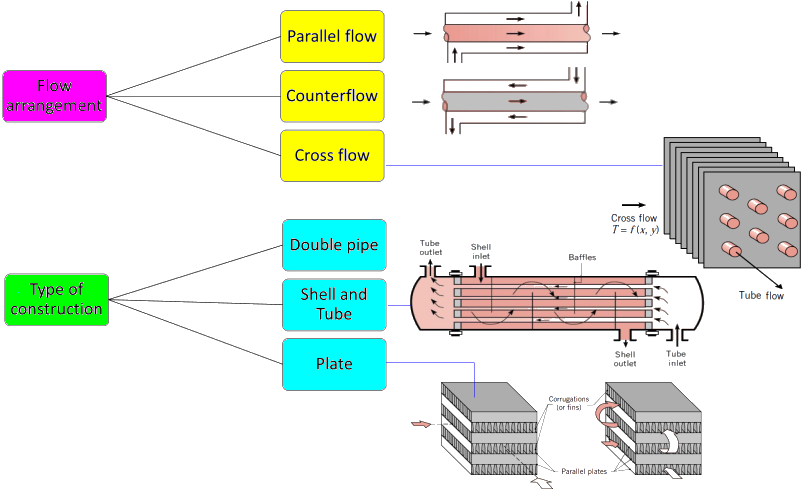
- Static Equipment: As the name suggests, there are no moving parts inside these components except moving fluid. The components falling under this category are pressure vessels, heat exchangers, tanks and filters, separators. Heat Exchangers are of the types: Air coolers and economizers, Plate and Frame, Spiral Plate, Shell and Tube, Plate-fin, Fired Heaters, Jacketed Pipe and Hair-pin.
- Rotating Equipment: The components falling under this category contains rotating parts and are primarily meant to move fluids. Rotating Equipments typically include assemblies like gas turbines, steam turbines, turbo-pumps, compressors, fans, motors, centrifuges... These equipment are distinguished by the rotating motion caused by impellers or rotors. In addition to the study of fluid and heat transfer phenomena, the effect of fluid on structural integrity of these parts is also important. Fluid-induced instabilities are one such phenomena which needs to be investigated.
- Fired Equipments: These are equipments which deals with combustion phenomena such as Furnaces, boilers, economizer
- Material Handling Equipment: cranes, hoists, conveyor systems and pulleys, Condensate tower, Vacuum tower, debutanizer, sour water stripper tower
Oil and Gas Industry
| Industry Segment | Main Operations | Players |
| Upstream | Oil exploration and owning of oil fields | Shell, ExxonMobil |
| Midstream | Field gathering (storage from thousands of bore wells), transmission pipelines, transportation vessels, processing plants | Halliburton, Reliance |
| Downstream | Distribution network for consumers: retail and industrial (e.g. aviation) | OMC: Oil Marketing Companies |
Spray Drier
Spray dryers have considerable importance in many industrial drying operations such as in food, detergent, minerals and pharmaceutical product processing. The key issues in dryer operation are:- Flow stability to avoid highly unsteady flows. Flow regimes of later typer can lead to significant wall deposition of partially dried product which sticks to the wall, resulting in a build up of crust.
- There are large scale drifting of droplets if the inlet flow is not swirled and regular precession occurs if there is inlet swirl
- Droplets in spray dryers contain solids and therefore modeling droplet evaporation should account for hindered drying due to the presence of the solids
- Amount of drying in most spray dryers is limited by equilibrium between the outlet gas and the dried particles as well as the particle drying kinetics
- Other important aspects of dryer operability are the accumulation of droplets/particles on the dryer walls or in the exit regions, particle agglomeration where near the nozzle liquid droplets coalesce but near the exit the partially dried solids can agglomerate.
- Almost all spray dryer modelling is performed using a mixed Eulerian/Lagrangian approach with single phase Reynolds Averaged Navier Stokes (RANS) equations are solved to determine the flow field.
- The phenomena is transient and three-dimensional in nature which require transient (time accurate) simulation methods
- The discrete phase, the wet droplets, are modelled using the Lagrangian technique and iterative coupling between the conservation equations for mass, momentum and energy is required because of the high inter-phase transfer rates.
- In transient simulations, droplets needs to be tracked for each time step along with storing positions and state (temperature, velocity, dryness) of the droplets. The injection of droplets are made at the inlet at each time step.
Jet Break-up
Excerpts from "REEVALUATING THE JET BREAKUP REGIME DIAGRAM" by Ben Trettel, University of Texas at Austin: "Breakup of Newtonian jets injected into still low density environments without considering cavitation, Mach number effects or evaporation, there are many varieties of jet breakup. Which regime a jet is in depends on factors including but not limited to the Reynolds number, Weber number, the liquid-gas density ratio and the turbulence intensity." 
- d0 = nozzle outlet diameter,
- xi = average breakup onset location
- θi = spray angle and
- xb = breakup length.
- Dripping regime: The jet velocity is so low that breakup is driven by gravity, producing relatively large droplets.
- Rayleigh regime: Breakup due to a surface-tension-driven instability resulting in droplets larger than the nozzle outlet diameter but of the same order of magnitude. The breakup length increases with increasing jet velocity.
- First wind-induced regime: Droplet diameters are on the order of the nozzle outlet diameter (Lin and Reitz). The breakup length decreases with increasing jet velocity in this regime (Reitz, 1978).
- Wind-induced regime: The droplet diameters are smaller than the nozzle outlet diameter. The average breakup onset location is not negligible, but can be small. The breakup length increases in a power law with increasing jet velocity.
- Atomization regime: Droplet sizes are much smaller than the nozzle outlet diameter, defined frequently as breakup starting at the nozzle outlet
Primary atomization of the liquid jet occurs near the outlet of the nozzle. Turbulent fluctuations of the liquid jet induce perturbations on the jet surface, which grow and break the jet into droplets. The length scale of turbulence is the dominant length scale of atomization, which also determines the resulting droplet size (Chryssakis et al.)1.
2In the plain-orifice atomizer model, the operation mode of the nozzle is determined based on the Reynolds number, the cavitation number and the critical values for the inception of cavitation and flipping (ANSYS, 2016). The Reynolds number based on hydraulic head is defined as ReH = (D ρL / μ) [2(p1 − p2)/ρL]0.5 where D is the nozzle diameter, ρL is the liquid density and μ is the liquid viscosity. The upstream and downstream pressures are denoted by p1 and p2, respectively. The cavitation number is defined as K = (p1 − pv)/(p1 − pv) where pv is the vapour pressure of liquid at operating temperature. For short, sharp-edged nozzles, the inception of cavitation occurs approximately at cavitation number K ~ 1.9.1Chryssakis, C.A., Assanis, D.N. and Tanner, F.X., 2011. Atomization Models, in Handbook of Atomization and Sprays, Ed. N. Ashgriz, Springer, New York, USA.
2ANSYS Fluent Theory Guide, section Atomizer Model Theory
Check Valves and Non-Return Valves
In general discussions, the designations ‘non-return valve’ and ‘check valve’ are used to mean the same device. However, as per "Heating and Plumbing Monthly" magazine, "There are legal requirements to use only check valves for backflow prevention. Fundamentally – check valves (CVs) and non-return valves (NRVs) are different fittings and serve different purposes. Under UK plumbing regulations, the check valve has a specific purpose as a device legally permitted to be used to prevent backflow in defined circumstances. The non-return valve, while useful for preventing reverse flow in pipes in many situations, is not a recognised backflow prevention device."
As per "hpmmag.com/training-and-technical/check-valves-and-non-return-valves":
Spool Valve
Reference: Flow-Force Analysis in a Hydraulic Sliding-Spool Valve by Niko Herakovic - 
The stationary share of the flow force for the inlet edge can be calculated from the axial momentum component as per equation (1). The non-stationary share of the flow force [necessary to accelerate the fluid mass in the slidingspool chamber] can be calculated using the length L of the accelerated oil quantity in the control volume of the sliding-spool chamber as per equation (2):

Safety Valves
The most widely used way to classify safety relief valves [SRV] is from the acting load on the valve disc.- direct spring-loaded safety valve, majority of cases in the industrial use
- weight loaded safety valve such as pressure cookers
- pilot operated safety valve - maintains constant pressure in a hydraulic system and is frequently used in precision hydraulic control systems

Reference: A CFD analysis of the dynamics of a direct-operated safety relief valve mounted on a pressure vessel by Xueguan Song et al. The motion of the valve disc is determined based from a force balance at all times which is governed by Newton's second law of motion resulting in second-order ordinary differential equation. Flow is mainly controlled by the opening between the nozzle and the disc until the disc attains the maximum lift. As the fluid is exhausted through the SRV, the average pressure inside of the vessel decreases proportionally consequently the lift force also reduces.

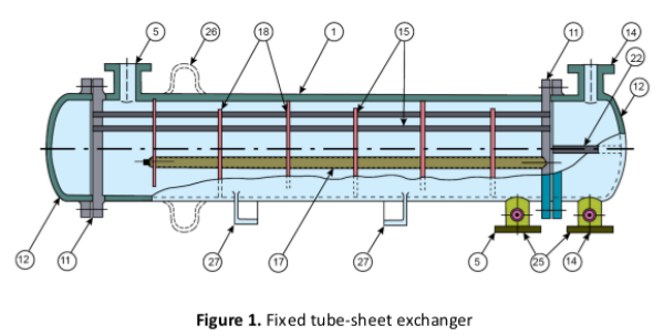
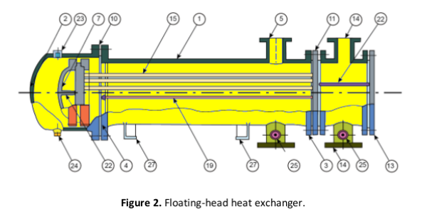
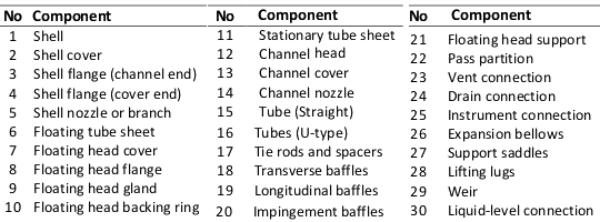
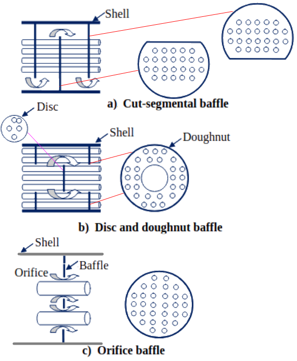
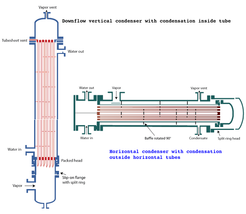
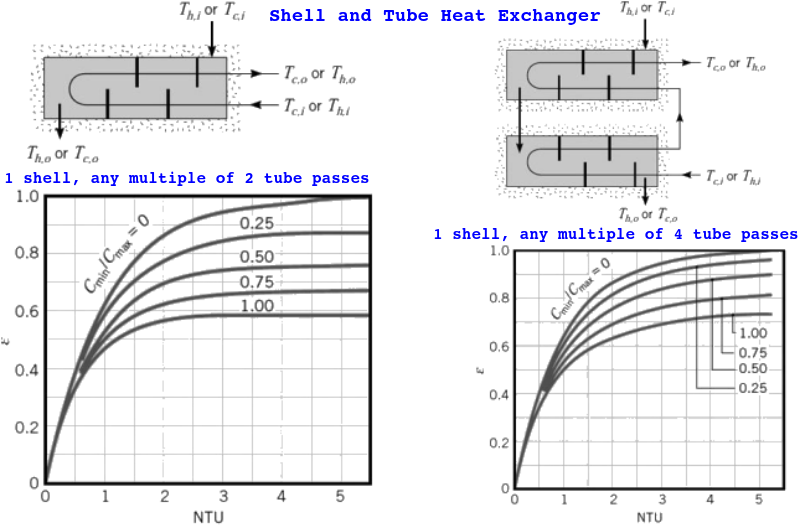
Shell and Tube Heat Exchangers
Reference from COMSOL Tutorial Guide:
Shell and Tube Condenser which is used in chiller application, condensate typically refrigerant is used to cool water below ≤ 15 [°C].
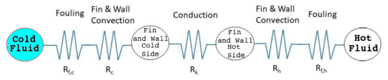
Methods for Sizing of Shell-and-Tube Heat Exchangers
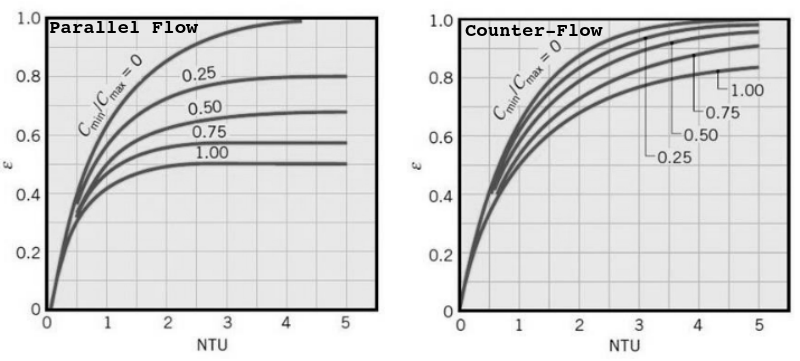
The LMTD method is a quick implementation for basic sizing of heat exchangers when the fluid inlet temperatures are known and the outlet temperatures are specified or can be determined from the energy balance. In case some fluid temperatures are unknown in advance, Effectiveness-Number Transfer Unit (ε-NTU) can be used. The method depends on number of passes, conditions of fluids (mixed, unmixed) and relative thermal capacities of the two streams.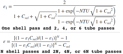
A simple Python code (under development - not tested or customized for all possible scenarios) for sizing of Shell-and-Tube Heat Exchanger is given below.
import math
'''
Input Variables (All in SI Unit, kg-m-s-[C] or [K])
Ignore the variables which are not needed based on the method chosen to size
the shell-and-tube heat exchanger (LMTD, e-NUT ...). For example, mass flow
rate is required only on hot or cold side for LTMD approach. Iterative method
is required when the inlet and outlet temperatures are not known or cannot be
easily calculated.

Note that for C_rel = 0, as in a boiler or condenser, the expression of
effectiveness is the same for all flow arrangement. Hence for such cases, heat
exchanger behaviour is independent of flow arrangement and type of construction

'''
arrangement = 'counter_flow'  # parallel_flow, cross_flow, shell_tube
n_shell_pass = 1

# Input for cold side
m_dot_cold = 1.2
T_in_cold  = 35.0
T_ex_cold  = 45.0
Cp_cold    = 4180
rho_cold   = 990
C_hot      = 'unmixed'       # For cross-flow: 'mixed' or 'unmixed'

# Input for hot size
m_dot_hot  = 1.0
T_in_hot   = 110.0
T_ex_hot   = 90.0
Cp_hot     = 1600.0
rho_hot    = 800.0
C_cold     = 'mixed'         # For cross-flow: 'mixed' or 'unmixed'
'''
Overall HTC in [W/m^2-K], v_tube = average velocity in tubes [m/s]
tube_side: hot or cold, tube_len_max = maximum permissible tube length
factor_F is the correction factor for number of passes. Ar_HX: aggregate
area of the primary and secondary, or finned, heat transfer surfaces.
'''
U_HTC      = 320.0
ID_tube    = 0.020
v_tube     = 0.250
tube_side  = 'hot'
n_pass     = 2
tube_len_max = 2.0

# Intermediate Variables
htx_cold_side = m_dot_cold * Cp_cold * (T_ex_cold - T_in_cold)
htx_hot_side  = m_dot_hot  * Cp_hot  * (T_ex_hot  - T_in_hot)
C_min = min(m_dot_cold * Cp_cold, m_dot_hot  * Cp_hot)
C_max = max(m_dot_cold * Cp_cold, m_dot_hot  * Cp_hot)

# Define flow streams mixing conditions for cross-flow arrangement
if C_min == m_dot_cold * Cp_cold:
  Cmin = C_cold
if C_max == m_dot_cold * Cp_cold:
  Cmax = C_cold
if C_min == m_dot_hot * Cp_hot:
  Cmin = C_hot
if C_max == m_dot_hot * Cp_hot:
  Cmax = C_hot

if C_hot == 'unmixed' and C_cold == 'unmixed':
  Cmin = 'unmixed'
  Cmax = 'unmixed'

C_rel = C_min / C_max

P     = (T_ex_cold  - T_in_cold) / (T_in_hot  - T_in_cold)
R     = (T_in_hot   - T_ex_hot)  / (T_ex_cold - T_in_cold)
K     = math.sqrt(R * R + 1)
F     = K * math.log((1 - P) / (1 - P*R)) / (R-1)
factor_F = F / math.log((2 - P * (R + 1 -K)) / (2 - P * (R + 1 + K)))

q_max = C_min * (T_in_hot - T_in_cold)
# Case-1:
# All the fluid temperatures are known, the LMTD can be calculated
if arrangement == 'parallel_flow':
  dT_hot  = T_in_hot  - T_in_cold
  dT_cold = T_ex_hot  - T_ex_cold
  LMTD = (dT_hot - dT_cold) / math.log(dT_hot / dT_cold)

elif arrangement == 'counter_flow':
  dT_hot  = T_in_hot  - T_ex_cold
  dT_cold = T_ex_hot  - T_in_cold
  LMTD = (dT_hot - dT_cold) / math.log(dT_hot / dT_cold)

else:
  dT_hot  = T_in_hot  - T_ex_cold
  dT_cold = T_ex_hot  - T_in_cold
  LMTD = (dT_hot - dT_cold) / math.log(dT_hot / dT_cold)
  LMTD = factor_F * LMTD

Ar_HX = htx_cold_side / U_HTC / LMTD / factor_F
print("\nRequired Area of heat-exchanger = ", round(Ar_HX, 2), "m^2 \n")

area_tube = math.pi/4 * ID_tube * ID_tube
if tube_side == 'hot':
  vol_flow_rate_tube = m_dot_hot / rho_hot / v_tube
else:
  vol_flow_rate_tube = m_dot_cold / rho_cold / v_tube

num_tube = round(vol_flow_rate_tube / area_tube)
len_tube = round(Ar_HX / math.pi / ID_tube / num_tube, 3)

if len_tube > tube_len_max:
  Ar_HX = htx_cold_side / U_HTC / LMTD / factor_F
  len_tube = round(Ar_HX / math.pi / ID_tube / num_tube / n_pass, 3)
print("Number of tubes = ", num_tube, "length of each tube = ", len_tube, "[m]")

# Effectiveness - NTU Method
NTU = U_HTC * Ar_HX / C_min

if arrangement == 'parallel_flow':
  effectiveness = (1 - 1/math.exp(NTU * (C_rel + 1) ) ) / (C_rel + 1)

if arrangement == 'counter_flow':
  if C_rel < 1:
    effectiveness = 1 - 1/math.exp(NTU * (1 - C_rel) )
    effectiveness = effectiveness / (1 - C_rel/math.exp(NTU * (1 - C_rel) ) )
  else:
    effectiveness = NTU / (1 + NTU)

if arrangement == "shell_tube":
  K1  = math.sqrt(1 + C_rel * C_rel)
  K2  = NTU * K1
  E1  = 2 / (1 + C_rel + K1 * (1 + math.exp(-K2)) / (1 - math.exp(K2)))
  if n_shell_pass == 1:
    effectiveness = E1
  else:
    exn = ( (1 - E1 * C_rel)/(1 - E1) ) ** n_shell_pass
    effectiveness = (exn - 1) / (exn - C_rel)

if arrangement == 'cross_flow':
  if Cmax == 'unmixed' and Cmin == 'unmixed':
    effectiveness = 1/math.exp(C_rel * NTU**0.78) - 1
    effectiveness = 1 - math.exp(effectiveness / C_rel * NTU**0.22)
  elif Cmax == 'mixed' and Cmin == 'unmixed':
    effectiveness = (1 - 1/math.exp(C_rel * (1 - 1/math.exp(NTU)))) / C_rel
  elif Cmax == 'unmixed' and Cmin == 'mixed':
    effectiveness = 1 - 1/math.exp(1/C_rel * (1 - 1/math.exp(C_rel * NTU)))
  else:
    print("Mixing status of fluid streams not defined!")

out = f"\nEffectiveness =  {effectiveness:0.3f} for NTU = {NTU:0.3f} and \
relative capacity ratio {C_rel:0.3f} \n"
print(out)

# Calculate NTU from known value of effectiveness
E       = P
xponent = 2/E - 1 - C_rel - (1 + C_rel**2)**0.5
xponent = xponent / (2/E - 1 - C_rel + (1 + C_rel**2)**0.5)
xponent = math.log(xponent)
NTU     = -(1 + C_rel**2)**(-0.5) * (xponent/2)
Flooded Evaporators
Shell-and-tube heat exchangers have multiple operating regimes: flooded or falling film evaporators of a water-cooled centrifugal chiller is one of the most complex ones, this is shown below referenced from "Measurement Method and Experimental Analysis of Liquid Entrainment for a Flooded Evaporator of a Water-Cooled Centrifugal Chiller Based on Energy Balance" by Huang et. al.
Operation and Design Variables from Public Domain
Reference-1 (FEV HP Series) --- Refrigerant charge: value of 2.7 lb/ton or (0.35 kg/kW), Shell diameter: 406 ~ 1016 mm (16 ~ 40 inch), Total length: 1800 ~ 4000 mm (6 ~ 13 feet), Design pressure on shell side: 18 [bar] gauge = 260 [psig], Design temperature on refrigerant side: -10 [°C], Tube material: copper, Shell material: Carbon steel.The content on CFDyna.com is being constantly refined and improvised with on-the-job experience, testing, and training. Examples might be simplified to improve insight into the physics and basic understanding. Linked pages, articles, references, and examples are constantly reviewed to reduce errors, but we cannot warrant full correctness of all content.
Template by OS Templates