- CFD, Fluid Flow, FEA, Heat/Mass Transfer
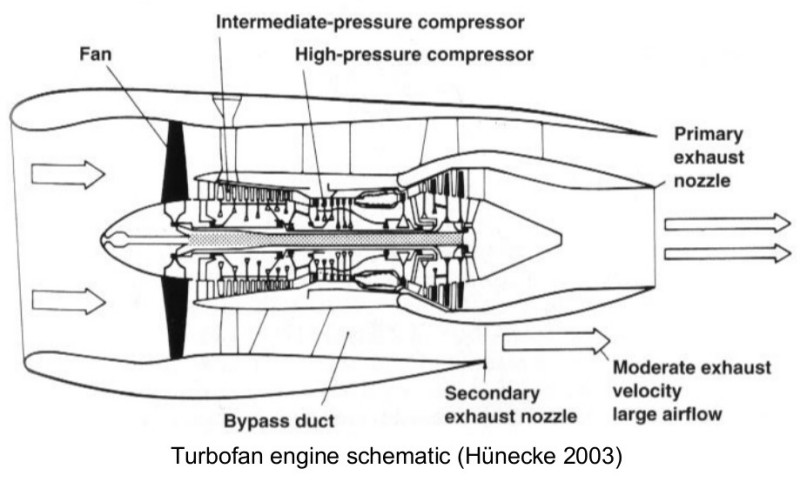
Gas Turbines and Aerofoils
External Aerodynamics: Parametric modeling of of an airfoil using blockMeshDict in OpenFOAM
Flow over Aerofoil
The construction of OpenFOAM cases for flow over an aerofoil can be done in many ways. For example, the tutorial section demonstrates two methods. The first method uses simpleFoam to demonstrate steady state and incompressible flow over the aerofoil. This method focuses on the overall methodology and a mesh generated in other application has been used. The second method as described in section compressible / sonicFoam / ras which uses a mesh created in STAR and utility star3ToFoam to convert the mesh to the OpenFOAM format. Yet another method using the data points of the airfoil and GMSH is explained in this tutorial.
This page contains information about flow simulations over aerofoil and gas turbine engines.
Gas Turbines in Images


Compressor Performance Characteristics
All the images are taken from AGARD LECTURE SERIES 183: Steady and Transient Performance Prediction of Gas Turbine Engines and the reference mentioned on the images are those in this paper.


Parametric Model of Airfoils
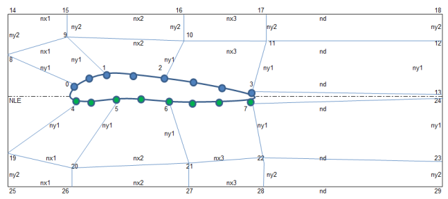
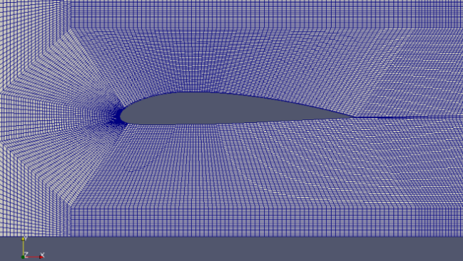
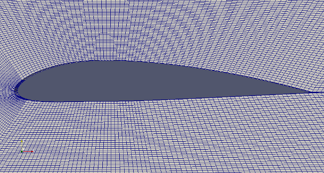
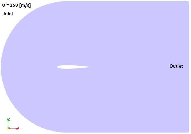
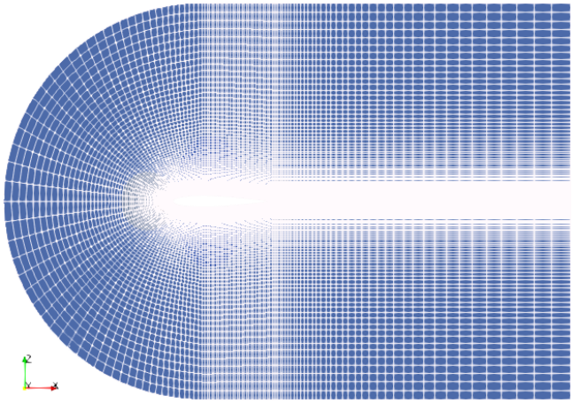
This page demonstrates a method which can be used to generate mesh for flow over an aerofoil when the points defining the cross-section of the aerofoil is known. The aerofoil shape is created using arc and spline utility of blockMesh. The entire domain will look like as shown below.
Check the effect of parameters on shape of the NACA airfoil:
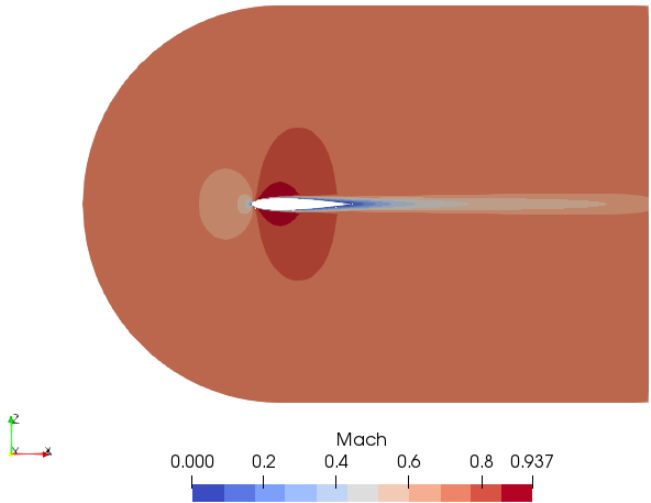
OpenFOAM v7 contains two tutorials: compressible\ rhoPimpleFoam\ RAS\ aerofoilNACA0012 and compressible\ rhoSimpleFoam\ aerofoilNACA0012 which use following computational domain.
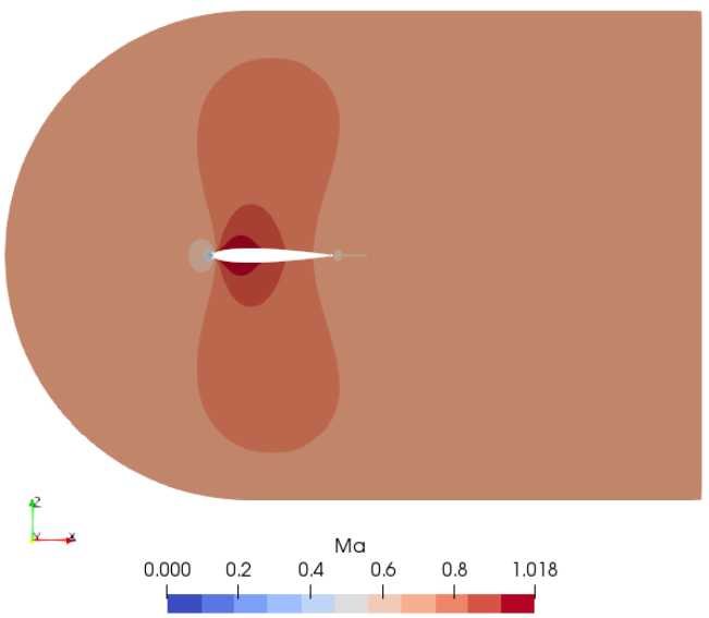
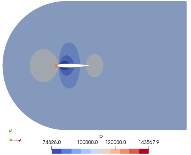
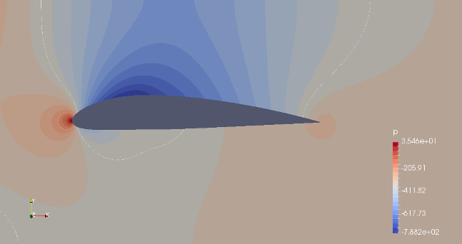
Mach number plot from SU2 simulation
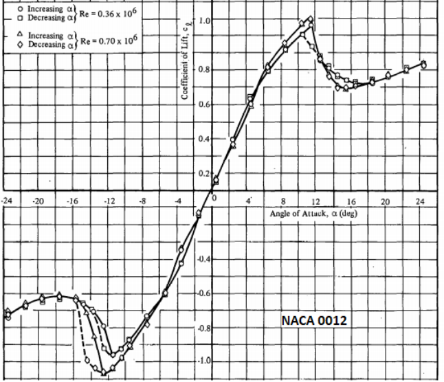
Lift Coefficient for NACA0012
Drag Coefficient for NACA0012
Reference: Aerodynamic Characteristics of Seven Symmetrical Airfoil Sections Through 180° Angle of Attack for Use in Aerodynamic Analysis of Vertical Axis Wind Turbines --- by Robert E. Sheldahl and Paul C. Klimas, Sandia National Laboratories. As per this report, the drag coefficient at AOA = 0° are tabulated below. Reynolds numbers are based on chord length.
| Reynolds number | Drag Coefficient |
| 10,000 | 0.0337 |
| 20,000 | 0.0245 |
| 40,000 | 0.0245 |
| 80,000 | 0.0133 |
| 1,60,000 | 0.0103 |
| 3,60,000 | 0.0079 |
| 7,00,000 | 0.0067 |
| 1.00E+06 | 0.0065 |
| 2.00E+06 | 0.0064 |
| 1.00E+07 | 0.0064 |
Aerodynamics: 2D Wing Theory
- R = Resultant force acting on the wing
- N = Component of R acting perpendicular to the chord
- A = Component of R acting parallel to the chord
- Lift L = Component of R acting perpendicular to the relative wind
- Drag D = Component of R acting parallel to the relative wind direction
- Angle of Attack, AoA: α = angle between the chord line and relative wind direction.
- L = N × cosα - A × sinα, D = N × sinα + A × cosα
- AWING (also designated as 'S' in many textbooks), Wing (projected) area: area of the wing responsible for lift
- Freestream density: ρ∞ = density of air flow over wings, Freestream velocity: V∞ = velocity of air flow over wings
- CL = Lift Coefficient, CD = Drag coefficient
- L = CL × ½ρ∞V∞2AWING, D = CD × ½ρ∞V∞2AWING
- At level flight: lift = weigth of aircraft (W), drag = thrust of the engine
- Wing loading, q = W / AWING
- Drag coefficient = [CD_i] induced drag (drag caused by shape responsible for generation of lift, includes that due to trailing edge vortex downstream the lifting surface) + [CD_o] zero-lift drag (drag due to shapes not contributing to generation of lift such as fuselage, cockpit...)
- Drag polar equation: CD = CD_o + K.CL2 where K = induced drag correcton factor and lift-dependent drag coefficient CD_i = K.CL2
- Steady level flight: Thrust (T) = Drag (D), Weight (W) = Lift (L). Thus: W = L = L/D × D = L/D × T
- Similarly, D = L × D/L = W × D/L = W × CD/CL. Thus, drag D would be minimum at maximum value of the ratio of CD/CL
- m: chordwise location for maximum ordinate of airfoil on camber line
- p: maximum ordinate of 2-digit camber line
- ζ = x/c, M = m/c, P = p/c, a NACA airfoil can be either of the form y/c = a0 ζ1/2 + a1 ζ + a2 ζ2 + a3 ζ3 + a4 ζ4 or y/c = M/P2 (2Pζ - ζ2) for 0≤ζ≤P, y/c = M/(1-P)2 (1-2P+2Pζ-ζ2) for P≤ζ≤1.
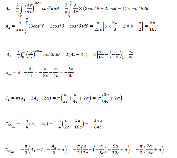
- CMLE: Pitching moment about leading edge
- CM1/4: Pitching moment about quarter-chord point
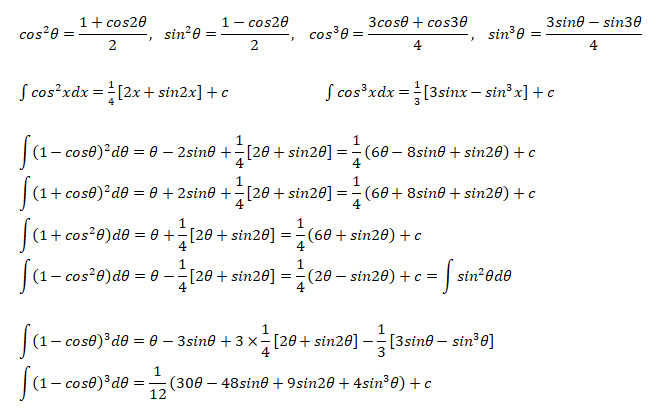
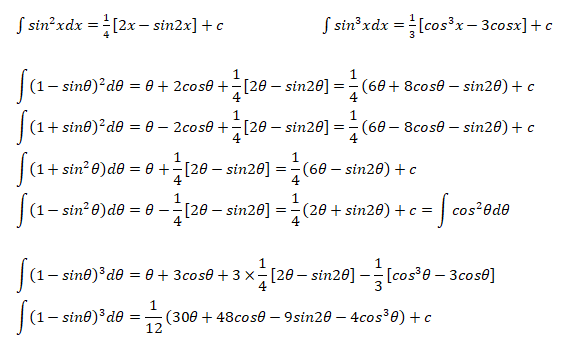
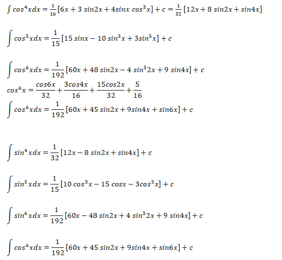
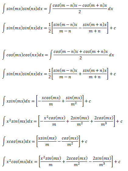
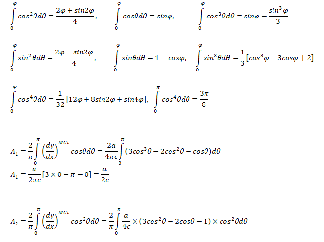
The following integration formula will be helpful in calculation of lift coefficient of airfoils.
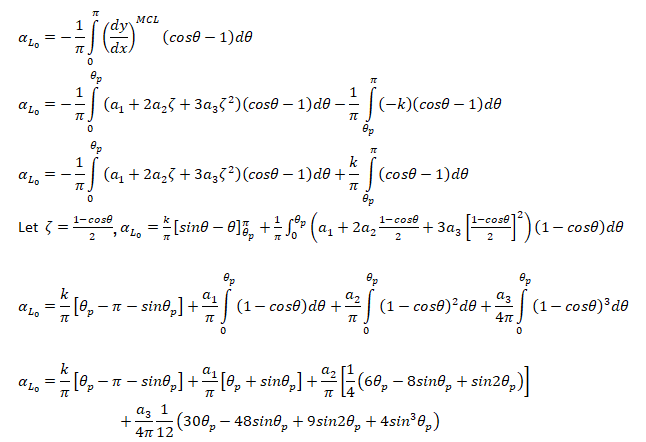
Calculation of Angle of Attack at Zero Lift
For small angle of attacks where MCL = Mean Camber Line: αL0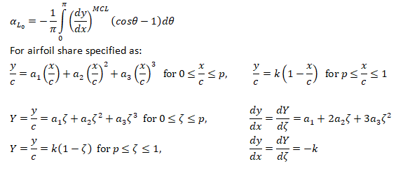
Formula: Lift Coefficient and Pitching Moment
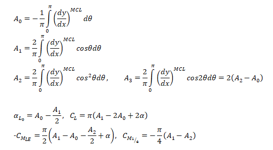
Lift Coefficient and Pitching Moment for a cubic Airfoil
The airfoil profile is given by cubic polynomial described below.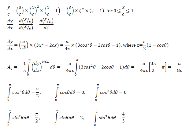
Pitching moment
- Pitching moment is positive when it tends to raise the nose of the aircraft upward. If Ma = pitching moment about a known distance 'a' from the leading edge 'LE' then: MLE = Ma - L × a × cosα - D × a × sinα ...[I] Similarly, pitching moment about a point away from LE by distance 'x': MLE = Mx - L · x · cosα - D · x · sinα ...[II]
- Subtracting equation [I] from [II]: Ma = Mx + (L × cosα + D × sinα) (a - x)
- CMx = CMa - (CL × cosα + CD × sinα) (a - x)/c ... [III]
- CMLE = CMa - (CL × cosα + CD × sinα) (a - 0)/c ... [IV]
- [III] - [IV]: CMx = CMLE + (CL × cosα + CD × sinα) x/c
Aerodynamic Centre: This is the point on chord at which CM is independent of CL. For angle of incidence up to 10 °, A.C. falls 20~25% behind the leading edge.
CMAC = CMa + (CL × cosα + CD × sinα) (xAC - a)/c
For small value of α, cos(α) ≈ 1 and sin(α) ≈ 0. Thus:CMAC = CMa + CL × cosα (xAC - a)/c
If a is chosen such that CL = 0, CMAC = CMa and hence pitching moment coefficient about an axis at ZERO LIFT equals the pitching moment coefficient about Aerodynamic Centre. Thus, CMAC is also designated as CM0, the moment coefficient at ZERO LIFT.Centre of Pressure: From equation [II], MLE = MAC - [L · cos(α) - D · sin(α)] · xAC
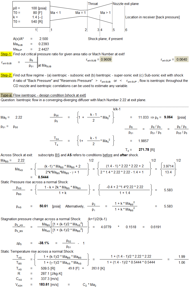
Converging-Diverging Nozzle:
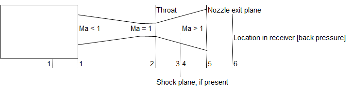
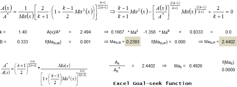
Problem Types:
- Type-a: Flow is isentropic thoughout, given Mach number at exit and area ratio calculate mass flow rate, temperature...
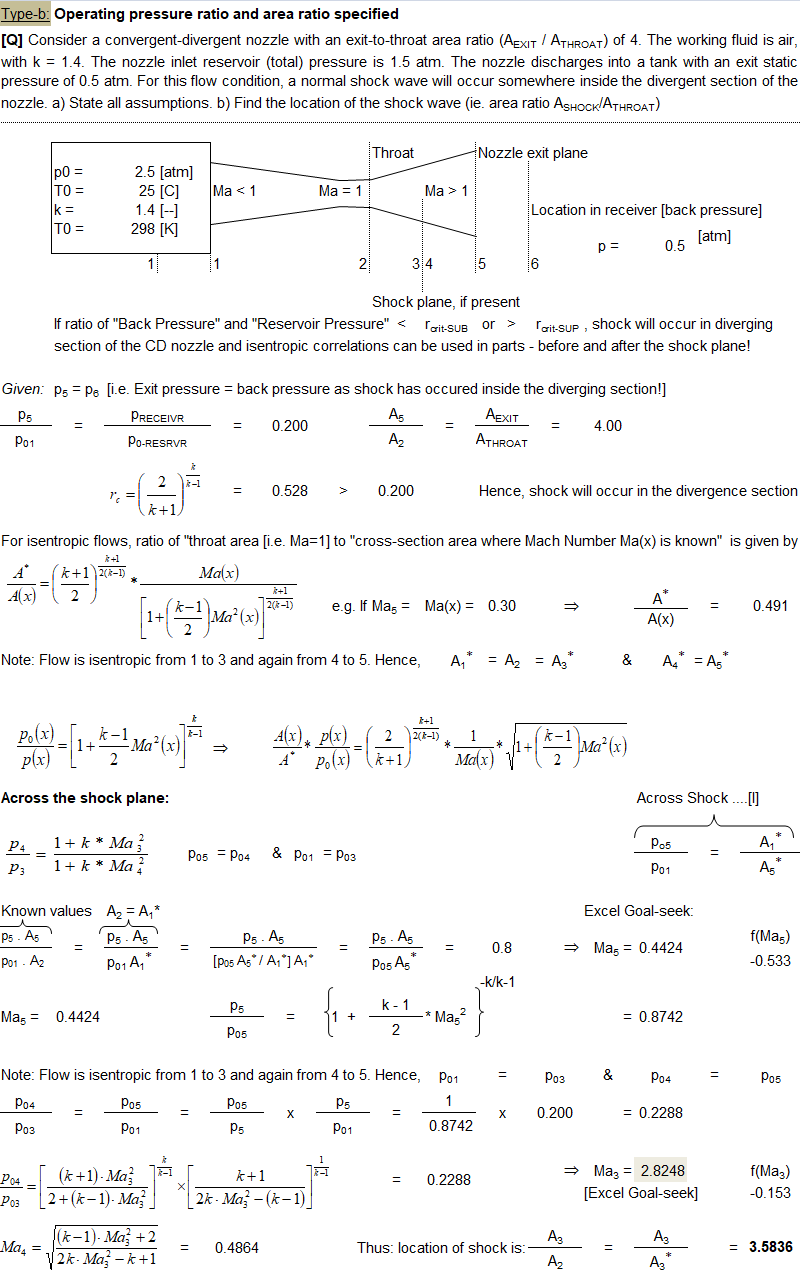
- Type-b: Given area ratio and operating pressure ratio, find out location of shock.
- Type-c: Area ratio and Mach number at exit is given, calculate operating pressure ratio.
- Type-d: Given location of shock and Ae/A*, find operating pressure ratio.
- Type-e: Design exit Mach number and reservoir pressure specified, calculate critical pressure ratios.
- Type-f: Given inlet conditions, exit//throat area ratio and Mach number before shock, find exit pressure, mass flow rate.
Type-a Problem:
Type-b Problem:
EXCEL VBA Script to Generate NACA Airfoil Coordinates
Option Explicit
Sub NACA_Profile()
  Dim nE, nN, nLE, nTe, i, K As Long
  Dim ytp(500), c, m, p, t As Double
  Dim x(500), dx, x1, y1, q, x3, yc, rt, ta, rExp As Double
  Dim XU(500), XL(500), YU(500), YL(500), ZU(500), ZL(500) As Double
  Dim yac(500), ybc(500), x2(500), theta(500), dx1, dx2 As Double
  Dim xp(500), yp(500), zp(500), xn(500), yn(500), zn(500) As Double
  Dim XUN(500), XLN(500), YUN(500), YLN(500) As Double

  '-----------------------------INPUT STARTS ----------------------------------
  c = 1 'c: Chord Length assumed 1, dimensions of aerofoil for any other length
        ' is simply the multiplication

  'Designmation of 4-digit NACA profile is: "NACA m-p-t" such as NACA 2412
  'm: MAX ordinate of mean line (in % of c)
  'NACA 4-digit -- p: Position of max ordinate (in tenths of c)
  'NACA 5-digit -- p: Position of MAX CAMBER in (2/100) of CHORD i.e. twice the
  '                    % of c
  't: MAX thickness of airfoil (as % of c)
  'Thus, the CAMBER & CHORDLINE of NACA 0012 will be straight coincident lines

  m = 4
  p = 3
  t = 14
  nN = 101
  'No. of points on chord, less than 500
  'No. of divisions on chord = n - 1
  '---------------------------INPUT ENDS------------------------------
  'Define points on the chord to capture aerofoil nose curvature
  x(1) = 0.0005
  x(2) = 0.002
  x(3) = 0.005
  x(4) = 0.01
  x(5) = 0.02

  dx2 = 0.8 / (nN - 5)
  nE = nN - 1
  i = 1
  Do While (i <= nE)

   'X-co-ordinate at ith division on chord
   If i >= 6 Then x(i) = x(5) + (i - 1) / (nE - 1)

   '-----Thickness of blade at ith location - The NACA 4-Digit Airfoil
   ytp(i) = (t / 100) * (1.4845 * (x(i)) ^ 0.5 - 0.63 * x(i) - 1.758 _
            * x(i) ^ 2 + 1.4215 * x(i) ^ 3 - 0.5075 * x(i) ^ 4)
   i = i + 1
  Loop

  'Calculate the y values for the mean (i.e. CAMBER) line
  i = 1 'Store y before MAX Camber
  K = 1 'Store y after  MAX Camber
  Do While (i <= nE)
    If (x(i) < (p / 10)) Then  'y before c
      ybc(i) = ((m / 100) / (p / 10) ^ 2) * (2 * (p / 10) * x(i) - x(i) ^ 2)

    Else                       'y after c
      yac(K) = ((m / 100) / (1 - (p / 10)) ^ 2) * (1 - 2 * (p / 10) + 2 * _
             (p / 10) * x(i) - x(i) ^ 2)

      K = K + 1
    End If
    i = i + 1
  Loop
  '------------------------------------------------------------------------------
  'Calculating the radius of the leading edge (LE)circle
  rt = 1.1019 * (t / 100) ^ 2

  'Calculate Trailing Edge Angle [Total Included Angle]
  ta = 2 * (Atn(1.16925 * t / 100))

  'Find y value of the line for the center of the nose circle w.r.t
  'standard x value of 0.005 (that is 0.5 % of Chord Length)
  x3 = 0.005
    If p = 0 Then
      yc = ((m / 100) / (1 - (p / 10)) ^ 2) * (1 - 2 * (p / 10) + 2 * (p / 10) _
         * x3 - x3 ^ 2)
    Else
      yc = ((m / 100) / (p / 10) ^ 2) * (2 * (p / 10) * x3 - x3 ^ 2)
    End If

  'Find angle of the line on which the center of the circle will lie on
  q = Atn(yc / x3)

  'Find the x coordinate for the center of the circle
  x1 = rt * Cos(q)

  'Find the y coordinate for the center of the circle
  y1 = rt * Sin(q)

  m = yc / x3
  dx = 2 * rt / 100
  x2(1) = 0
    For i = 2 To nE
      x2(i) = x2(i - 1) + dx
    Next i

  i = 1
  Do While (i <= nE)
    xp(i) = x2(i)
    yp(i) = ((rt ^ 2 - (x2(i) - x1) ^ 2) + y1) ^ 0.5
	'Positive y values of the circle
    zp(i) = 0
    xn(i) = x2(i)
    yn(i) = -((rt ^ 2 - (x2(i) - x1) ^ 2) + y1) ^ 0.5
	'Negative y values of the circle
    zn(i) = 0
    i = i + 1
  Loop

  '------------------------------------------------------------------------------
  yp(1) = 0    'Starting airfoil at 0 for nose
  yn(1) = 0    'Starting airfoil at 0 for nose

  'Calculating the upper and lower coordinates of the airfoil
  i = 1
  K = 1
  Do While (i <= nE)
    If (i = 1) Then
      XU(i) = x(i) 'Tip of Airfoil nose is Origin
      YU(i) = x(i)
      ZU(i) = 0
      XL(i) = x(i) 'Tip: Lower & Upper surface intersect tangentially
      YL(i) = x(i)
      ZL(i) = 0
      theta(i) = 0
    ElseIf i > 1 And x(i) < (p / 10) Then
	  'When x-cordinate is less than that at MAX Camber
      theta(i) = Atn((ybc(i) - ybc(i - 1)) / (x(i) - x(i - 1)))
      XU(i) = x(i) - ytp(i) * Sin(theta(i))
      YU(i) = ybc(i) + ytp(i) * Cos(theta(i))
      ZU(i) = 0
      XL(i) = x(i) + ytp(i) * Sin(theta(i))
      YL(i) = ybc(i) - ytp(i) * Cos(theta(i))
      ZL(i) = 0
    Else
      If (K = 1 And p = 0) Then
        theta(i) = Atn((yac(K) - 0) / (x(i) - x(i - 1)))
        XU(i) = x(i) - ytp(i) * Sin(theta(i))
        YU(i) = yac(K) + ytp(i) * Cos(theta(i))
        ZU(i) = 0
        XL(i) = x(i) + ytp(i) * Sin(theta(i))
        YL(i) = yac(K) - ytp(i) * Cos(theta(i))
        ZL(i) = 0
        i = i + 1
      ElseIf K = 1 Then   'That is where two parabola meet
        theta(i) = Atn((yac(K) - ybc(i - 1)) / (x(i) - x(i - 1)))
        XU(i) = x(i) - ytp(i) * Sin(theta(i))
        YU(i) = yac(K) + ytp(i) * Cos(theta(i))
        ZU(i) = 0
        XL(i) = x(i) + ytp(i) * Sin(theta(i))
        YL(i) = yac(K) - ytp(i) * Cos(theta(i))
        ZL(i) = 0
        K = K + 1
      Else                'Calculate co-ordinate after MAX camber value
        theta(i) = Atn((yac(K) - yac(K - 1)) / (x(i) - x(i - 1)))
        XU(i) = x(i) - ytp(i) * Sin(theta(i))
        YU(i) = yac(K) + ytp(i) * Cos(theta(i))
        ZU(i) = 0
        XL(i) = x(i) + ytp(i) * Sin(theta(i))
        YL(i) = yac(K) - ytp(i) * Cos(theta(i))
        ZL(i) = 0
        K = K + 1
      End If
    End If
    i = i + 1
  Loop

  XU(nN) = 1  'Ending airfoil at exactly unit length
  XL(nN) = 1  'Ending airfoil at exactly unit length

  Dim sh As Boolean
  With ThisWorkbook
   For i = 1 To .Sheets.Count
    If .Sheets(i).Name = "NACA" Then
      sh = True
      Exit For
    End If
   Next i

   If sh = False Then
    Worksheets.Add(After:=Sheets(Worksheets.Count)).Name = "NACA"
   End If
  End With

  Dim ws As Worksheet
  Set ws = ThisWorkbook.Worksheets("NACA")
  ws.Cells(2, 1).Value = "S. No."
  ws.Cells(2, 2).Value = "XU(i) / C"
  ws.Cells(2, 3).Value = "YU(i) / C"
  ws.Cells(2, 4).Value = "ZU(i) / C"
  ws.Cells(2, 5).Value = "XL(i) / C"
  ws.Cells(2, 6).Value = "YL(i) / C"
  ws.Cells(2, 7).Value = "ZL(i) / C"
  ws.Cells(2, 8).Value = "ytp(i)"

  i = 1
  K = 1
  Do While (i <= nE)
    ws.Cells(2 + i, 1).Value = i
    ws.Cells(2 + i, 2).Value = XU(i)
    ws.Cells(2 + i, 3).Value = YU(i)
    ws.Cells(2 + i, 4).Value = ZU(i)
    ws.Cells(2 + i, 5).Value = XL(i)
    ws.Cells(2 + i, 6).Value = YL(i)
    ws.Cells(2 + i, 7).Value = ZU(i)
    ws.Cells(2 + i, 8).Value = ytp(i)
    i = i + 1
  Loop

  Range("A:A").HorizontalAlignment = xlCenter
  Range("B3:H3").Select
  Range(Selection, Selection.End(xlDown)).Select
  Selection.NumberFormat = "0.00000"
  With Selection
   .HorizontalAlignment = xlCenter
   .VerticalAlignment = xlCenter
   .WrapText = False
   .Orientation = 0
   .AddIndent = False
   .IndentLevel = 0
   .ShrinkToFit = False
   .ReadingOrder = xlContext
   .MergeCells = False
  End With
End Sub
References:
- FAA-RD-79-51: Titanium Combustion in Turbine Engines
- AFAPL-TR-78-52: The Aerothermodynamics of Aircraft Gas Turbine Engines
- FTD-MT-24-306-70: Combustion Chambers of Gas Turbine Engines
- RTO MEETING PROCEEDINGS 8: Design Principles and Methods for Aircraft Gas Turbine Engines
- NASA/TM—2005-213658 - "Parametric (On-Design) Cycle Analysis for a Separate-Exhaust Turbofan Engine With Interstage Turbine Burner" by Liew et. al.
- AGARD LECTURE SERIES 183: Steady and Transient Performance Prediction of Gas Turbine Engines
- Fundamental Modelling of Reacting Flow in Ramjet Dump Combustors
The content on CFDyna.com is being constantly refined and improvised with on-the-job experience, testing, and training. Examples might be simplified to improve insight into the physics and basic understanding. Linked pages, articles, references, and examples are constantly reviewed to reduce errors, but we cannot warrant full correctness of all content.
Template by OS Templates