- CFD, Fluid Flow, FEA, Heat/Mass Transfer: Feedbacks/Queries -
Mesh Generation Process
Mesh Generation
Meshing for CFD is 50% capability and 50% art!

Table of Contents:
Mesh Size Estimation | Mesh Quality | Mesh Generation Steps | Pre-processing: FLUENT Mesher | TUI for CAD geometry Import |:| Settings for Prism or Boundary Layers | Mesh Generation in ANSA | Mesh Formats | COMSOL Meshing | Volume Mesh Setting in FLUENT Mesher | Mesh to Geometry | Workbench Meshing | Meshing in TurboGrid | Wrapping in FLUENT Mesher | Periodic Mesh | View Volume Elements on Iso-planes | Meshing Thin Gaps | Polyhedral or Mosaic Meshing ]=[ Pre-processing: Geometry Clean-up [:] Retain Face Names during STEP Conversion
Selection of Entities in FLUENT Mesher |:| Query Functions |:| Remove Gaps between Faces |:| Mesh Diagnostics |:| Mesh Summary Report |:| Generate Volume Mesh in Batch Mode |:| Types of elements |:| Mesh Generation Methods |:| Global vs. Local Join and Intersect Operation |:| Leak Detection |:| Fill Volume or Generate Mesh one Volume at a Time |:| Refine Volume Mesh |:| MultiZone Meshing in Workbench |:| Blender for Geometry Clean-up
Rename Cell Zones |-| Body of Influence (BOI) |:| Read STL File in FLUENT Mesher [*] Watertight Meshing Workflow ]*[ Example: Meshing in Batch Mode |:| Split cells and zones |:| Fill Holes |:| Project Nodes and Elements
Definitions in Pre-processors
Solid modeling (required to create 3D geometry) and mesh generation are at present separate steps, performed using different programs and software environment and a greater seamless integration is still in distant future. The first step of meshing is to ensure the "topological consistency" of the 3D geometry when the data is transferred from "Solid Modelling" environment such as ANSYS SpaceClaim, Creo, SolidWorks to "Mesh Generation" environment such as FLUENT Mesher, ANSA, Hypermesh. The topology refers to the way points, lines and surfaces connect to form a three-dimensional space. However, different nomenclature suh as Assembly, Component, Body, Parts, Multi-body Parts, Zones, Boundaries... make it a bit difficult to navigate from one tool to other.
It is a must to know the differences to even understand the User Guide. In Design Modeler and hence in ANSYS Meshing, part and bodies are represented as shown below.

Body refers to individual (independent and not open or closed) volumes. Part is 'assembly' of bodies. In ANSYS Discovery (SpaceClaim), Component refers to Collection of Components and Bodies. Anything under "Structure tree" contained within a top-level design component (root part), are called Objects.
The understanding of geometrical terms is important to know the idea when one reads: "Use Shared Topology to connect two or more bodies to form a single, continuous body while preserving interfaces." or "Ansys Workbench meshing cannot mesh bodies that are part of the same part independently of each other, since by definition of being in the same part, they will be meshed conformally." or "Assembly tools work on components." or "For component with multiple bodies in SpaceClaim, different share topology options are available in the bottom left menu: none, group, share and merge."
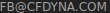
Mesh Generation Timeline
From project management and schedule/cost point of view, there are two important criteria. The first one is that should the computational domain extraction be performed in CAD environment or be a part pre-processing step? While it is expected that a water-tight volume as an input to simulation engineer would be helpful, it is not always the case. One needs to get familiar with the geometry anyway. The middle approach is to get partial cleaning-up (removal of bolts, filling holes...) in CAD environment and let the simulation engineer extract the domain. It make him/her familiar with the geometry while performing this activity.
Checklist of Volume Extraction and Mesh Generation before Exporting to Solver Format
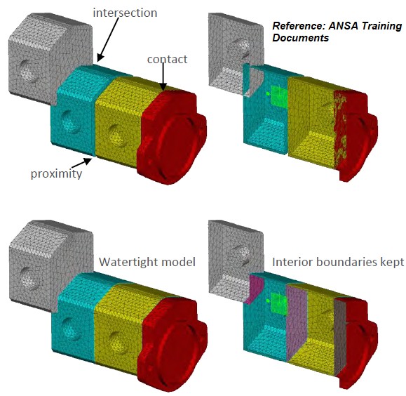
Refer to this page for geometry clean-up tips and method to estimate effort. Note that free-edges, self-intersection and sometimes highly skewed boundary cells can be easily corrected in mesh generation tools, proximities are the most difficult to handle. Hence, first check the user should make after importing the CAD geometry into pre-processor is to check for proximity issues and cells high skewness ≥ 0.99.
Check that the names defined in geometry are translated correctly and as-expected in meshing tool - if not redefine the names in geometry. This helps reduce the likelihood of wrong zone name selections during pre-processing in solver settings.
| S. No. | Checkpoint | Record [Y / N / NA] |
| 01 | Has the number of volumetric regions* matched with number of bodies in input geometry? | |
| 02 | Has the mesh quality been checked for skewness and aspect ratios (for boundary layers and for free-stream elements)? | |
| 03 | Have sliver elements been collapsed? With minimum size ~ 0.05 [mm], elements having area < 0.002 [mm2] or volume 0.0001 [mm3] are unreasonable. | |
| 04 | Have the fluid and solid zones named as per material type say by adding air, ss, al, pl, cr (ceramics)... as suffix? Have the wall names added with prefix prism_ for boundary layer creation? | |
| 05 | Have appropriate prefixes been added to boundary names as per type: e.g. mf_ for mass-flow, vi_ for velocity inlets, po_ for pressure outlets... hub, shroud, periodic, interface, rotating, rough... for walls | |
| 06 | Have the areas of the boundaries been checked and matched with the values used to estimate boundary condition parameters? | |
| 07 | Have the walls been grouped into logical surface-groups, such as hsrc_ / empt_ / pcbw_ / sink_ / hflx_... to make it easy to maintain during solution and post-processing? Read note-1 for FLUENT. | |
| 08 | Have the inlet and outlet planes of a porous domain been assigned to separate internal patches? Have the fan plane created with suffix such as cw_z or ccw_z based on direction of rotation and axis? | |
| 09 | Has the maximum volume of elements been checked to confirm consistent refinement? Check mesh statistics and compare with reference value. | |
| 10 | Have the volume mesh zone names cleaned to remove numerical suffix added by FLUENT? In case it could not addressed through Named Selection, use this script to rename the cells zones. |
Note-1: When a Named Selection is created by selecting faces that belong to different bodies, after import into Fluent, the named selection is split into multiple zone and boundary condition needs to be applied on each of the zones separately. To avoid such segmentation of same boundary type, in addition to creating named selection for the required faces, named selection should be created for the bodies to which these faces belong to. When the mesh is imported into Fluent, the bodies that are now in the named selection are treated as a single cell zone and hence the boundary faces that were part of the named selection are not split.
Marking cells with high skewness value (such as ≥ 0.95) shall highlight / mark only few cells omitting adjacent elements. It is recommended to use threshold value of 0.70 and scan through the groups of boundary faces that need to be collapsed or remeshed.
Depending upon the mesher and geometry, try to use aspect ratio or area to filter out degenerate faces instead of using skewness for quality improvement.In FLUENT Meshing, select a boundary zone (instead of default option to select all) to mark faces with bad quality - the "collapse all" operation can be used without affecting other zones.
Sometimes, it is acceptable to have poor quality cells in the final mesh. The quality of volume elements is usually worse than the quality of surface elements. Hence, to get a minimum orthogonality of 0.05, the skewness and aspect ratio of surface elements should be ≤ 0.85 and 20 respectively.
In case orifices are to be modeled, the refinement along perimeter is critical. Note that analytical area is higher than the discretized area and difference reduces as refinement increases. The deviation or ratio of "discretized area / analytical area" with respect to number of divisions of the perimeter is tabulated below where ratio = n * sin(θ)/2/π where n is number of divisions and θ = 2π/n.
| n | 6 | 8 | 10 | 12 | 16 | 20 | 25 | 32 | 50 |
| Area ratio: | 0.8270 | 0.9003 | 0.9355 | 0.9549 | 0.9745 | 0.9836 | 0.9895 | 0.9936 | 0.9974 |
Go to geometry clean-up steps or refer to checklist for solver set-up and update geometry / mesh appropriately. A quick look at post-processing report temperature and checklist shall help update the geometry to expedite post-processing operations.
Meshing is not same as Tessellation
This step involves division of the computational domain into small sub-divisions called a grid or mesh of cells/elements/control volumes. The 2D boundaries of this smaller (discretized) domains are called Faces, the 1D boundaries are called Edges and 0-D boundaries are called Nodes or Vertices. The solution of flow problems are defined at nodes or face centres of the cells. In general, the accuracy of CFD simulation is governed by cell size. Finer the mesh (lower the cell size), better is the result. However, hardware requirement (RAM, number of cores) increases with increase in no. of cells (elements) in the mesh. Hence, a trade-off is required.
- The mesh resolution near walls affect calculation of wall shear as well as separation zone and location of separation. Appropriate mesh sizing is critical because fidelity of local wall shear predictions affects the prediction of frictional drag for external flows or pressure drop (which is also a form of frictional drag) for internal flows. Both the frictional and pressure drag for bluff bodies is dependent upon extent of separation zones.
- When you use the Spalart-Allmaras model or any other eddy-viscosity model with enhanced wall function, you should check that y+ of the wall-adjacent cells is either very small (on the order of y+ = 1), or y+ ≥ 30.
- The requirement of a non-uniform mesh is a necessity and not a limitation. The cell size should be smaller in the regions of sharp gradients of field variables (velocity, pressure, temperature, shear stress) and larger in the regions of lesser gradients.
- Though the regions of sharp gradients cannot be anticipated a priori, this is based on the user's experience where an insight into the physics of the problem is helpful.
- Most modern solvers come with a feature called "mesh-adaption". The solver automatically refines the mesh based on various setting such as y+ refinement. However care should be taken so that enough memory is available after such refinements as the mesh size (no. of cells / elements) can increase significantly after such adaptation.
- If machine time in computation is ignored, it takes approximately 75% of the overall simulation time in a good mesh generation, which include geometry clean-up.
Some of the jargon associated with meshing are:
- Bi-directional associativity between CAD environment and pre-processing environment: This refers to automatic updation of mesh when associated CAD geometry is updated.
- Virtual topologysuch as slicing in Ansys Workbench, imprint in STAR-CCM+: This refer to changing the geometry to suit meshing requirements without affecting the underlying geometrical description. Note that there is a difference the way CAD environment treats geometrical entities and the way mesh generator software use those information.
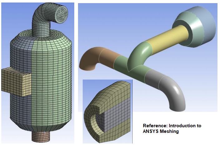
- Swept meshing, Multi-zone meshing, Paving, Blocking: different approach and methods to generate mesh. For example, sweeping is generating 3D mesh from a 2D mesh by rotational or translational extrusion (sweep) of mesh between two geometrically similar ends. For example, a conical cylinder or U-bend may have different diameters at the two ends still a sweeping operation can be used to generate the mesh.
Mesh by Extrusion
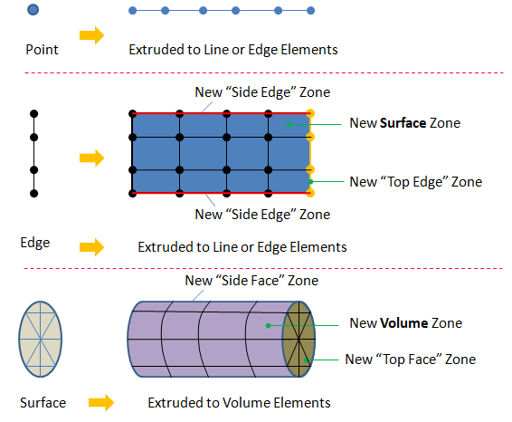
- Feature Lines: these refers to the edges or lines which determines the loss of tangency or curvature continuity in the surfaces. In generic terms, these refers to edges of a geometry.
- Proximity Detection: This refers to the small gaps between two surfaces or can be within a surface itself. For example, modeling the tyres (a perfect cylinder) of a car on a flat road. Theoretically, there would be a point contact between the tyre and the road surface.
Types of elements
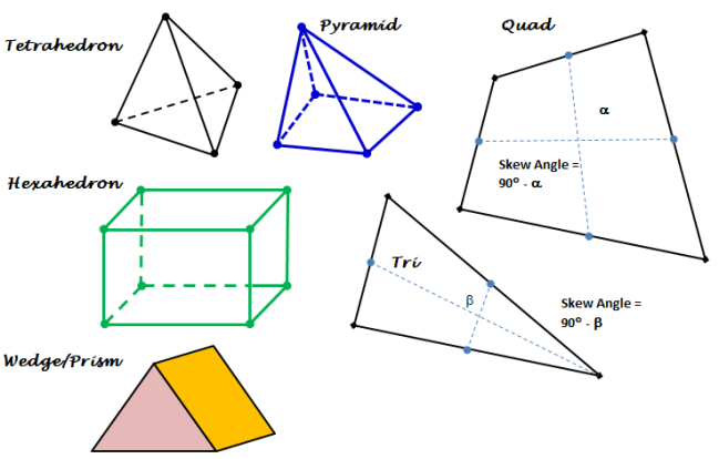
Note that a node is a 0-D element, an edge is an 1-D element, triangles and quadrilaterals are 2-D elements and tetrahedrons, hexahedrons, pyramids and wedges are 3-D elements. The 2-D elements which constitute the boundaries of a 3-D elements are called faces. Element which define the boundary of a computational domain will always have dimension 1 less than the dimension of the flow domain. For example, for 1-D cases the boundaries will be represented by nodes, for 2-D cases the boundaries will be of type edge elements and for 3-D cases the boundaries will have 2D elements.
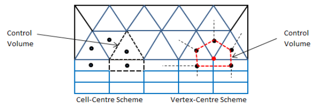
The elements defining the flow domains other than boundaries are called interior elements. Note that the mesh topology used to specify simulation parameters may be different than the mesh topology internally created by the solver. For example, a solver may create a mesh around each node by connecting the centroids of all the elements associated with it. This is called a vertex-based scheme (e.g. CFX). In some cases, the mesh supplied to the solver will be used as provided such as FLUENT. This is known as cell-centred scheme.
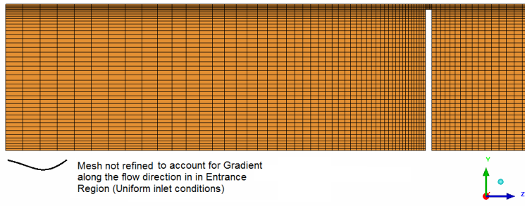
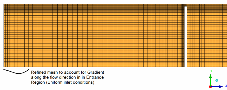
One important consideration in generating mesh is also to capture the physics of the flow. Most of the time, we are focused on the boundary layer resolution over the walls and near the separation and reattachment regions. The underlying principle is to capture the gradient of field variables, in whatever direction they might be present. One such similar consideration is flow gradient in the entrance region when "uniform flow velocity" is to be applied. Here the gradient is along the direction of flow, similar to the one we observe perpendicular to the wall. Following images demonstrates the recommended mesh in the entrance region.
Flow-Field Dependency: The effect of mesh quality (refinement and cell shape) on the accuracy and convergence of the solution process is dependent on the flow field being simulated. E.g. highly skewed or non-orthogonal cells can be tolerated in flow regions with no swirl or separation. On the other hand same mesh can be detrimental to simulation accuracy in regions with strong flow (pressure) gradients.
Since the locations of strong flow gradients generally cannot be determined a priori, user needs to guess the flow field based on his/her past experiences as well as using analogy between actual flow field and standard flow conditions namely "flow over a cylinder", flow over a flat plate, "flow inside a duct" and flow between parallel plates.
Mesh Size Estimation
This is a simple calculator to estimate total number of elements expected during mesh generation step. The value shall help users check the limitation on memory size (RAM) of their workstations. For example, a 32 [GB] RAM machine may handle a volume mesh consisting of approx. 50 million "prism + tetrahedrons" or less.
| Total surface area excluding internal walls/baffles: | [m2] | |
| Total volume of computational domain: | [m3] | |
| Surface mesh type: | [ - ] | |
| Volume mesh type: | [ - ] | |
| Typical surface mesh size: | [mm] | |
| Typical volume mesh size: | [mm] | |
| Number of prism layers: | [no.] | |
| Average prism layer height: | [mm] | |
| Maximum volume mesh size: | [mm] | |
| *** | ||
Mesh Types
A mesh is designated as structured, unstructured, hybrid, overset, conformal or non-conformal. These are based on the connectivity of the cells, nodes and edges. One of the misunderstanding is that a mesh consisting of only quad elements are always structured. This is not true and a structured mesh is identified by a pattern where each node is connected to same number of elements.A mesh consisting of more than 1 element types such as tetrahedrons and hexahedrons are called hybrid. They may or may not be conformal. In case a hybrid mesh consisting of tetrahedrons and hexahedrons are conformal, pyramid elements need to be used to transition from tetra to hexa elements.
A non-conformal mesh has grid nodes which do not match up along an interface. This type of mesh is useful for design study where parts can be replaced without regeneration of the entire mesh. Sometimes, this type of mesh becomes a necessity for meshing complex geometries. Recommended approach to have number of nodes / elements in the ratio 2:1 or less on the two sides of a non-conformal interface.Mesh Generation Methods / Algorithms: the two broadest categories of mesh are (a)structured mesh and (b)unstructured mesh. As the names suggest, structured mesh has a unique, predictable and repeatable topology whereas unstructured mesh is a pseudo-random distribution of element in space. Structured meshes are composed of either quadrilaterals or hexahedrals. Unstructured mesh can be a combination of all types of elements. Yet, a mesh consisting of only hexahedrals can also be unstructured mesh.
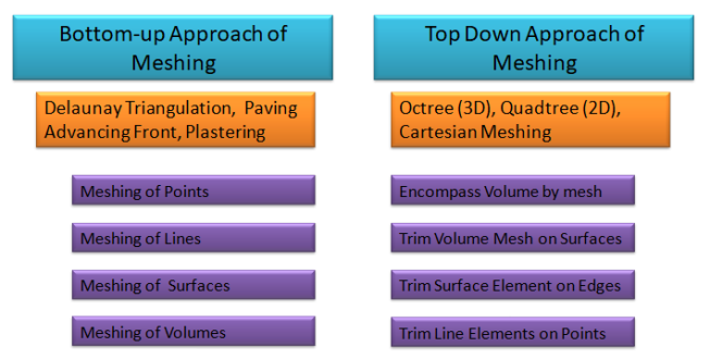
There are various mesh generation algorithms available in industry: OCTREE (QUADTREE), Delaunay, Advancing Front, Directed Meshing (Swept Meshing), Cut-Cell or Cartesian or snappyHexMesh, Paving, Multi-zone, Hexa-core ... to name few. Directed meshing techniques work on extrudable geometry: this refers to shapes which can be generated by linear (translational) and rotational or combination of both operation on a lower dimension geometry to get a higher dimension geometry. For example, a frustum is a linear extrusion of circular disk in radial as well as tangential direction, a cylinder is a uniform extrusion of circular disk, a circular disk is rotational extrusion of a line about one of its ends. The extrusion process is also known as sweeping or lofting operation.
- Body must have topologically identical faces on two ends (which act as source and target faces). Rotational Sweep bodies are not identified automatically in ANSYS Mesher.
- Side faces must be mappable - such as a trapezoidal or cylindrical faces.
- Only one source and one target face can be used per sweep operation.
- In ANSYS Meshing, automatic identification of source and target faces is not compatible with inflation layer generation. Selection of source and target faces manually is compatible with inflation layer generation. One must specify at least Source face manually when using Inflation and Sweep Method since 2D inflation defined on source face from boundary edges is swept through volume, source must therefore be specified first.
- Rotational sweeping requires both Source and Target face to be selected manually.
Mesh Quality
Recommendation from ANSYS FLUENT: For any other software, it is recommended to check the rating scale. For example, ICEM CFD considers skewness of 1.0 as perfect and scale is exactly opposite to that of FLUENT.
| Skewness | 0 | 0 ~ 0.25 | 0.25 ~ 0.50 | 0.50 ~ 0.75 | 0.75 ~ 0.95 | 0.95 ~ 1.00 | 1.00 |
| Category | Perfect | Excellent | Good | Fair | Poor | Very Poor | Degenerate |
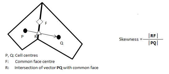
Verbatim copy form ANSYS FLUENT 12.0/12.1 Documentation: Skewness is defined as the difference between the shape of the cell and the shape of an equilateral cell of equivalent volume. Highly skewed cells can decrease accuracy and destabilize the solution. For example, optimal quadrilateral meshes will have vertex angles close to 90°, while triangular meshes should preferably have angles of close to 60° and have all angles less than 90°.
- A general rule is that the maximum skewness for a triangular/tetrahedral mesh in most flows should be kept below 0.95, with an average value that is less than 0.33.
- A maximum value above 0.95 may lead to convergence difficulties and may require changing the solver controls, such as reducing under-relaxation factors and/or switching to the pressure-based coupled solver.
Verbatim copy form ANSYS FLUENT 12.0/12.1 Documentation: Aspect ratio is a measure of the stretching of the cell. For highly anisotropic flows, extreme aspect ratios may yield accurate results with fewer cells.
- Generally, it is best to avoid aspect ratios in excess of 5:1 in the bulk flow (away from the walls).
- The quadrilateral/hexahedral/wedge cells inside the boundary layer, on the other hand can be stretched to aspect ratio of up to 10:1 in most cases.
- With regard to the stability of the flow solution, it can go as high as possible; however with regard to the stability of the energy solution, the maximum aspect ratio should be kept below 35:1.
Hanging Node
A surface is bounded by edges and edges are connected at vertices or key points or nodes. So, a rectangular surface is bound by 4 edges and the 4 edges themselves make 4 corners and thus 4 nodes, vertices or key points. Any straight edge of surface must be a connection between two nodes. Any node not meeting this requirement is called a a "hanging node" as described below.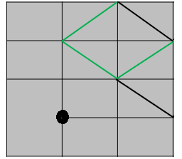
Non-Manifold Vertices (Nodes)
A mesh or finite element representation of a real geometry is a connection of edges and points in a certain way. When the connection is representing a real geometry, it is said to be topologically correct. However, since edges and point can be connected in any arbitrary manner, they may not always represent the physically plausible geometry. Thus:a non-manifold geometry or 3D shape cannot be unfolded into a 2D surface with all its normals pointing the same direction. In other words, a 3D model can be represented digitally but there is no geometry which can physically support it in the real world. In the following picture, a hexahedral element has internal tetrahedral element which is not necessary at all.
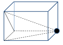
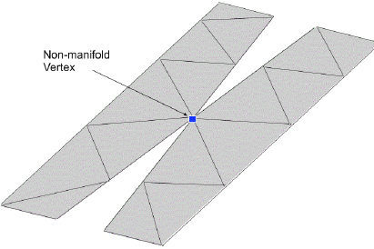
Similarly, if a vertex is attached to the interior of a surface or if surrounded by a volume but not connected with any of the edges defining that volume, it is called a non-manifold vertex.
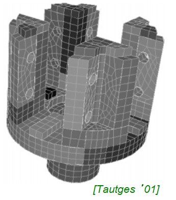
All hexa mesh in T- and Y-Junction
The O-grid techniques can be used to generate hexahedron meshed in complicated geometries such as Tee-junctions and Wye-junctions as demonstrated in following image.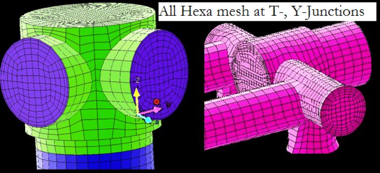
For complex geometries such as engine under-hood thermal management, structured mesh quad/hex meshes are neither possible nor show any numerical advantage, thus one can save meshing effort by using a mesh consisting of tri/tetra elements.
Mesh Quality Parameters
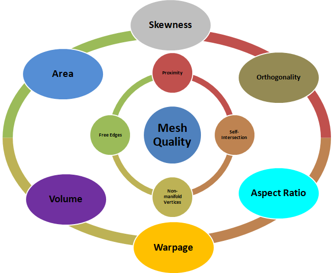
Warp: It applies only to quadrilateral elements and is defined as the variation of normals between the two triangular faces that can be constructed from the quadrilateral face. Warp value is the maximum of the two possible ways triangles can be created in a quadrilateral/rectangular face.
Various checks required to ensure the geometrical and topological consistency of a mesh is completely described by the options available in ANSYS ICEM CFD as shown below. Similar checks is possible in any other software such as ANSA, ANSYS Meshing, Pointwise and GridPro.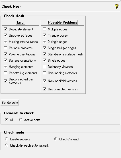
For a tetrahedron mesh, the maximum skewness shall not be better than the maximum face skewness because the skewness of boundary cells (tetrahedrons) is limited by the skewness of boundary faces (triangles).
Read STL File in FLUENT Mesher: Faceted geometry are stored in many different formats such as STL, OBJ and PLY. FLUENT Meshing is designed to work with surface bodies and hence faceted geometry can be directly read/imported. One option is to use ANSYS Discovery to convert the data in STL format into a TGF (FLUENT Meshing faceted geometry) format and then read/import it in FM. Another option is to directly import STL data as CAD Object. It will give warning: "Note that cad faceting and CFD surface mesh does not apply for STL (.stl) files. Note that Length Unit conversion does not apply for STL (.stl), ACIS (.sat, .sab) and AutoCAD (*.dwg, *.dxf) formats. They will be imported in whatever units they were created."
STl representation of a geometry is mesh-based and all surfaces of a body are imported (read) as a single surface. Hence, all named selections do not get imported. However, all the body names defined in the model tree shall be exported as separate surface bodies.Polyhedral or Mosaic Meshing
Many meshing companies and software providers claim that polyhedral meshes are the ultimate remedy of all meshing problems. More myth has got associated with this mesh than the problem they solve or make the life of analysts easier. Reference: Tips and tricks in OpenFOAM. Note that Polyhedral meshing algorithms uses underlying tri and quad elements. Hence, refinement of poly mesh is proportional to refinement of the tri and quad mesh over which it is built.Polyhedral mesh requires less cells than a tetrahedral, but that is just because each cell is equivalent to multiple tetra, so the comparison is not on a common metric for the grid resolution. Polyhedral cells certainly introduce less distortions as compared to tetra, and hence they have higher cell quality. Other advantages typically mentioned for polyhedral cells refer also to the capability of better representing gradients (because of multiple neighbours) and different flow alignments. But this typically overlooks the fact that derivatives are calculated in the Cartesian directions, not along the flow directions.
As in version 242, Fluent meshing throws error if non-manifold vertices are found in the surface mesh: ["2" non-manifold point contacts are detected in the mesh object "..". Poly and Poly-hexcore volume meshing are not compatible with non-manifold contacts. Use the Point Contact Diagnostic Tool to resolve the non-manifold contacts.] There is no option named "Point Contact Diagnostic Tool" though proximity check shall lead to the elements which are part of non-manifold vertices.- In polyhedral meshes the cells have more neighbours than in tetrahedral and hexahedral meshes, hence the gradients are approximated better on polyhedral meshes
- A hexahedral cell demands more CPU and memory than a tetrahedral cell
- Polyhedral meshes reduce the cell count significantly but increase the number of faces. Thus, solver need to compute more fluxes (diffusive and convective). There is no significant saving in run-time excluding troubleshooting times
- Polyhedral meshes are not easy to generate, most of the times one need an starting tetrahedral or hexaheral meshes
- Polyhedral meshes inherits the same quality problems of the starting tetrahedral mesh and sometimes may made things worse
- There is no data published by software vendors to prove that polyhedral meshes are better than hexahedral or tetrahedral meshes!
As per CD-ADAPCO STAR-CCM+ User Guide Version 9.06, 2015: STAR-CCM+ polyhedral elements have an average of 14 faces and five times less polyhedral elements are needed for a given volume compared to tetrahedral elements.
A mesh was generated (without prism layers) in two a domain comprising of two cylinders of dimension (im mm) φ5 x 50 and φ10 x 50. The number of boundary and internal nodes/faces are summarized below. This is to give an indication about features of the two types of meshes and cannot be used to make any conclusion. Tetrahedrons Polyhedrons
----------------------- ----------------------
Boundary Interior Boundary Interior
----------------------- ----------------------
Nodes 27,433 2,15,803 81,893 13,29,308
Faces 54,066 27,10,769 27,429 16,47,332
Cells - 13,68,901 - 2,46,604
A closer look of boundary elements in a poly mesh shall reveal that the elements comprise of pentagons, hexagons and heptagons. Also, a polygon is created around the vertices of triangles by connecting the centroids of connected triangles.
Tetrahedrons: Their advantage is the ease of its generation even in case of very complex geometry. On the other hand tetrahedrons cannot be stretched excessively without decreasing the mesh quality factor, so a significantly larger number of cells has to be used in comparison to hexahedral mesh in order to achieve a reasonable accuracy. Moreover the numerical diffusion of tetrahedral elements is significantly higher.
Polyhedral cells: Combine the advantages of hexahedrons (low numerical diffusion resulting in accurate solution) and tetrahedrons (rapid semi-automatic generation) as well as to overcome the disadvantages of both the above mentioned mesh types. The major benefit of polyhedra l mesh is that each individual cell has many (> 4) neighbours, so gradients can be well approximated than is the case with tetrahedral cells. Polyhedrons are also less sensitive to stretching than tetrahedrons which results in better mesh quality leading to improved numerical stability of the model. In addition, numerical diffusion is reduced due to mass exchange over numerous faces. This lads to a more accurate solution achieved with a lower cell count.
Even along wall edges and at corners, a polyhedral cell is likely to have a couple of neighbours, thus allowing for a reasonable prediction of both gradients and local flow distribution. However, more neighbours means more storage and computing operations per cell than is the case with tetrahedral cells.Polyhedral mesh cannot be used in ANSYS CFX. However, CFX being node-based solver, control volumes around nodes are polyhedral cells created internally when input mesh is of type tetrahedrons. For a hexahedral mesh as input, the created control volumes will be also of hexahedral type.
Watertight Meshing Workflow
Water-tight refers to a 'topologically' closed geometry with no leakage (gap between edges) and valid Share Topology between various bodies. This means the check operations like self-intersection, overlapping faces... are not required to be performed in this workflow.
As per video titled "Fluent: Watertight Geometry Meshing Workflow" from "ANSYS How To" series, at timestamp 4:20 it explains that the region attached to capping surfaces (surfaces associated with boundary conditions) are automatically assigned as type 'fluid'. Thus, though the geometry should have shared topology, the conditions of fluid domain defined as solid body in SpaceClaim should not apply. A fluid region can be a surface body which can be deemed a closed (water-tight) body if its free edges are closed by solid body through share topology operations (not a universal approach though and some cases might required fluid volume as closed solid body connected with solid domains through Share Topology operation).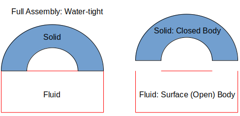
| Watertight Geometry Workflow | Fault-tolerant Workflow |
| Prerequisite: clean watertight geometry with all surfaces properly connected - named selections and topology shared at CAD level | Prerequisite: None - Tolerant to bad quality CAD/STL, handles dirty and non-watertight geometries |
| Main features: Conformal CHT mesh, Supports surface mesh file as input | Main features: Wrapping technology automatically handles gaps, unstitched surfaces and overlaps, Non-conformal CHT mesh |
Watertight Workflow Steps

The SpaceClaim and Discovery applications are not supported on Linux as in version 2024. Hence, any script to use Linux cluster for geometrical operations shall not work. The CAD geometry needs to be exported in *.pmdb (Parametric Model Database) format in FLUENT Mesher. Script Workbench.Fluent .ExportPMDB(r "E:\Projects\Case-1.pmdb") can be used. Or using PyAnsys as follows":
from ansys.geometry.core import Modeler
from ansys.geometry.core import launch_modeler_with_discovery
from ansys.geometry.core import launch_modeler_with_spaceclaim
scdm = launch_modeler_with_spaceclaim(product_version=232, hidden=True)
design = scdm.open_file(r"E:\Projects\Case-1.scdoc")
#scdm.read_existing_design()
#scdm.run_discovery_script_file(file_path = r"E:\Projects\Script.py", script_args = {})
design.export_to_pmdb(r"E:\Projects")
scdm.exit()
Note that exporting geometry to neutral formats such as STEP, IGES or STL may not work is Share Topology operation is required (such as conjugate heat transfer cases). Fluent Meshing and Workbench Meshing shall recognize the Share Topology operation which does not get transferred into STEP or STL formats. However, Named Selections shall not get transferred from SCDM to STEP - only the component and body names shall get transferred. Other options to be explored are to use Fluent Meshing faceted geometry (*.tgf) format which works on Faceted Geometry having same format as a .msh file and FM Database (*.fmd) - for input to the Fault Tolerant Meshing Workflow.
Option suggested in Fluent User's Guide: "On Windows, use the Import CAD Geometry dialog to import the CAD file into Fluent, and enable the Save PMDB (Intermediary File) option in the Import Options dialog. After the file is imported, move the generated .pmdb file over to Linux system for use in (watertight or any other) workflow." Use TUI /file/import/cad-options save-PMDB? yes before importing CAD geometry. Note PMDB in capitals.
1. Import Geometry: file/import/cad-geometry "Geom.pmdb" - import CAD files based on the options set, for a single file (default) specify the file path. Set up options for the length unit, tessellation method, and sizing parameters based on the tessellation method.
2. Add Local Sizing: scoped-sizing/create - defines the scoped size based on the specified parameters. "size-functions/create curvature face wall_x wall_y , sf_curvature 0.05 0.75 1.25 6.0" where curvature is the size function type, face indicates that face zones are to be used, wall_x, wall_y indicate the boundary zones for which the size function is defined, and sf_curvature is the size function name. The remaining values correspond to the parameters for the curvature size function minimum and maximum size, growth rate, and normal angle. /size-functions/create proximity face (*) "sf_proximity" 0.1 2.5 1.2 3 face-face yes yes
Defining curvature sizing for all object face zones except symmetry planes: /scoped-sizing/create sf_curv curvature object-faces yes no "(eval-expr '(list-subtract (get-objects-of-filter '*) (get-objects-of-filter 'sym*) ) )" 0.25 4 1.2 6. Refer sample script for object-based meshing.3. Create Surface Mesh: boundary/remesh/remesh-face-zones-conformally - remeshes face zones using the current size function and keeping a conformal interface between them.
4.0 Describe Geometry: not applicable for object-base meshing (outline approach).
4.0.1 Update Boundaries: boundary/manage/type to change boundary type to inlet, outlet, periodic, internal, symmetry...
4.0.2 Set Up Periodic Boundaries, if Applicable: boundary/set-periodicity translation dx dy dz - defines the periodicity parameters, prompts for the type of periodicity (rotational or translational) and x-, y-, z-translation values. Other method is /boundary/make-periodic no dx dy dz () per_1 per_z (). boundary/recover-periodic-surfaces - restores the periodic relationship between face zones. Recovering periodic surfaces for mesh object face zones: /boundary/recover-periodic-surfaces auto (get-face-zones-of-label '_fluid '(period_1)). GUI method Boundary > Manage... > Options > Change Type does not have entry 'Periodic' in the drop-down under 'Type'.
4.0.3 Create Regions: objects/volumetric-regions/compute - Compute the volumetric regions based on the face zone labels, existing material points for computing the regions can be specified.
4.1 Update Regions: objects/volumetric-regions/change-type - change region type to fluid or solid (default). Utility function (tgapi-util-get-region-name-list-of-pattern "object_name" "sol*") may be used to identify volume starting with 'sol'.
5.0 Add Boundary Layers: /mesh/scoped-prisms create bl_all_walls uniform 0.05 3 1.25 object_name fluid-region grow-on only-walls. Option for growth: uniform (first layer height : number of layers : growth rate), aspect-ratio (first layer aspect ratio : number of layers : growth rate), last-ratio. Options for scope to: fluid-regions, named-regions, solid-regions. Options for zone: only-walls, all-zones, selected-face-zones, solid-fluid-interface, selected-labels.
6.0 Generate Volume Mesh: /mesh/poly/controls cell-sizing geometric 1.2 and then generate poly-mesh: /mesh/auto-mesh object_name yes pyramids poly yes. Rename mesh zones to keep it consistent for all iterations: mesh/manage/name (fluid*) fluid_air. Use (get-zones-of-type 'type) to get fluid and solid zones if only one of each type is present. Save mesh file: /file/write-mesh vMesh.msh.h5
The workflow can be read in batch mode as well. The %py-exec command is used within the Scripting Console to execute Python code that automates parts of the meshing workflow. Following code shall not work without graphics due to use of .Execute() method.(%py-exec "workflow.LoadWorkflow(FilePath=r'WTM_WkFlow.wft')")
(%py-exec "workflow.TaskObject['Import Geometry'].Arguments.setState(1)")
(%py-exec "workflow.TaskObject['Import Geometry'].Arguments.GeometryFileName = 'Geom.scdoc'")
(%py-exec "workflow.TaskObject['Import Geometry'].Execute()")
;(%py-exec "workflow.TaskObject['Import Geometry'].Arguments.setState({r'FileName': r'Geom.scdoc'})")
(%py-exec "workflow.TaskObject['Add Local Sizing'].Execute()")
(%py-exec "workflow.TaskObject['Generate Surface Mesh'].Execute()")
(%py-exec "workflow.TaskObject['Describe Geometry'].Execute()")
(%py-exec "workflow.TaskObject['Update Boundaries'].Execute()")
(%py-exec "workflow.TaskObject['Set Up Periodic Boundaries'].Execute()")
(%py-exec "workflow.TaskObject['Add Boundary Layers'].Execute()")
(%py-exec "workflow.TaskObject['Generate the Volume Mesh'].Execute()")
;(%py-exec "workflow.TaskObject['Generate the Volume Mesh'].ExecuteUpstreamNonExecutedAndThisTask()")
To see all available task names in the workflow: (%py-exec "print(workflow.TaskObject.keys())")
TUI Steps to create conformal periodic boundaries:
- Delete one of the pair of the periodic zones defined in surface mesh (created through Named Selection in SpaceClaim): boundary manage delete periodic_zn_2 () yes
- Create a (translational in x-direction) periodic shadow pair: boundary manage make-periodic no 20 0 0 periodic_zn_1 ()
- Create object from a shadow zone created in previous step: object create periodic_shadow fluid () shadow* () () mesh yes
- Merge object created for shadow zone with main object: object merge main_object_name periodic_shadow () main_object_name
- Merge free nodes between periodic_shadow and adjacent zones: boundary merge-nodes (*) (*) yes yes yes 10: questions answered through yes are: check only free nodes, with only free nodes, percent of shortest connected edge length tolerance
Mesh Generation Steps
Naming Convection of Boundaries and Cell Zones: In any practical application of CFD simulations, the computational domain may comprise of many cells zones (fluid and solid zones) and boundary zones (walls, inlets and outlets). The engineer responsible for pre-processing may not be the one who creates solver file and post-processes the results. The reviewer(s) of the mesh and simulation set-up will certainly be not the engineer who created them. In order to convey the domain information seamlessly, a naming convention should be adopted, it can be a generic system applicable for large number of projects or a specific system for particular simulation set-up. An example is outlined below with following default setting: Newtonian, stationary, adiabatic, smooth boundaries or zones can be named arbitrarily though it is recommended to chose names and identifiers meaningfully.Naming Convention
- Inlet(s) and outlet(s) should be named as b_vi_inlet_id, b_mf_outlet_id... where 'id' stands for identifier such as location name. Type 'vi' for velocity inlet, 'mf' for mass flow outlet...
- Walls with specific boundary conditions (other than adiabatic): w_tpr_id, w_hfx_id, w_htc_id, w_rot_id w_mov_id, w_rgh_id, w_s2s_id where 'rgh' stands for rough walls, s2s stands for coupled solid walls.
- Cell zones: fld_air_id, fld_wtr_id, fld_oil_id, fld_nnw_id, fld_rot_id, por_xdir_id, por_zdir_id, sld_alm_id, sld_stl_id, sld_src_id ... where 'nnw' stands for non-Newtonian fluids, 'src' stands for solid zones with heat source and/or sink and 'por' stands for porous (fluid) zones.
- Internal planes: int_f2f_id, int_baf_id ... where 'baf' stands for thin walls or baffles. Internal walls are monitoring and/or post-processing planes created during mesh generation process itself.
- Non-conformal interfaces: if_f2f_id, if_s2s_id, if_sta_rot_id, if_por_fld_id, if_sol_fld_id where 'sta' stands for 'stationary' zones and 'por' stands for 'porous' zones.
- All boundaries with no special setting or conditions to be applied on them can be named as 'b_empty_id'.
When 'Computing' volumes in FLUENT meshing, the default type assigned is 'solid'. Similarly, combining different mesh files from different mesh cells into one Ansys Fluent cell, Ansys Fluent assigns 'solid' type to all cell zones even though these were designated as 'fluid' in meshing. To change this default behaviour of assigning a 'solid' type to all cell zones, create Named Selections in CAD geometry and/or meshing and give the fluid zone names a prefix such as 'fluid_' to these named selections.
Pre-processing: Geometry Clean-up
All pre-processing tools have to deal with geometrical issues which are designated differently in different programs. CAD Geometry issues defined in ANSYS SpaceClaim are: Curve gaps, Duplicate curves, Small curves, Small faces (slivers), Inexact edges, Extra edges, Split edges, Gaps and Missing faces. Colour codes used to identify geometry issues are: single (free edge) - red, double edge - blue, triple edge: magenta, multiple edge - yellow. In FLUENT mesher, the colour schemes are Free face / edge - blue, Multi-face / edge: yellow.It is also recommended to align the model in such a way that the front view covers the maximum information and the alignment of front view is inline with that defined in pre-processor. For example, front view in FLUENT mesher is defined as XY plane with Z-axis point outward from the screen, the left view is YZ plane with Z-axis pointing into the plane of the screen and top view is the ZX plane with Y-axis pointing outward from the screen. This definition is not universal and some program use YZ as front view.
Another challenge and often leading to confusion is the "Jargon" used in CAD and Meshing software to represent geometry (solid, surfaces and assemblies). CAD entities are designated as 'Components' and 'Bodies'. Components refer to 'Assembly', 'Sub-assembly' and 'Part'. 'Bodies' are basic entities in a CAD assembly tree which include CAD zones. This list gets compounded when one adds the terms "Geometry Objects", "Mesh Objects", "Face Zone Labels", regions, boundaries, continuum / continua, PID, collectors...
In design and manufacturing field, 'part', 'component' and 'body' are used interchangeably. They refer to a physical object which cannot be broken down further. E.g. a sheet metal bracket, a bolt or a nut is a 'component'. Similarly, impeller or shaft is a 'component' but the water pump is an 'assembly'. The water pump in an engine is a 'sub-assembly' and 'engine' itself is an 'assembly'.Often geometry exchange between CAD and CFD tools happen through STEP format. The STEP format supports named entities which can be created within CAD environment such as inlet face, outlet boundary, walls with known temperature... To define 'names' in PTC Creo, the design can use: File > Prepare > Open Model Properties, then select 'Names' in the model properties dialogue. Then select faces by clicking > enter a name in the dialogue box opened in previous step. During CAD export to STEP format with default settings, the 'names' defined earlier do not get stored in the file. Change the export setup through File > Options > Configuration Editor > intf_out_assign_names > set it to 'user_name'.
The pre-processing activities require geometry simplifications (de-featuring) and ANSYS SpaceClaim has some powerful non-parametric features. One of them is the 'Pull' option (short-cut 'p') which is equivalent to 'sweep' or 'extrude' operation. By default, pull direction is tangent to the selected edge or perpendicular to the selected face. A direction can be chosen or pulled (sweep) along a curve. Selection: all holes equal to selected radius, all holes of same radius in same face, all holes of radius equal or smaller than select radius. Blend (b): create surface by two lines (it is equivalent to 'loft' operation in some CAD programs). Fill (f): create surface from a closed loop of curves. Move (m): the 'origin' option is to select the reference point on the source object.
When multiple solid bodies exist in a single Component (SpaceClaim) or Part (DesignModeler), Shared Topology is used by the mesher to have shared nodes coincident face that connects the two bodies back into a single mesh.Many a times, circular arc gets converted into splines during data conversion (export- import) operations. In such cases, the measurement features shall print only the edge length and not the radius. Following simple calculator can be used to estimate radius with curve/edge length.
| Specify curve edge length: | [unit] | |
| Specify included angle: | [deg] | |
Units in Imported Geometry
No CFD pre-processor and solver can work on concept of "Consistent Unit System". The units for all the inputs need to be specified explicitly. Thus, every CAD import operation within CFD environment have option to choose the units to work - this will automatically convert the dimensions from the length unit of CAD geometry being imported into the new length unit.
Steps of Geometry De-featuring
The steps (as well as tips and tricks) described here is based on simplifications features available in ANSYS Spaceclaim though it applies to any pre-processing tool. This acts as a checklist before geometry is transferred to pre-processor (mesh generation environment). For cases where ANSA and STAR-CCM+ are used, ANSA is equivalent to SpaceClaim and STAR-CCM+ is equivalent to FLUENT Mesher. Blender is another (fully) open-source program to clean geometry and convert the CAD model into STL type (water-tight) surface mesh. FreeCAD and gradCAD are few of the open-source CAD tools that can be used to create and modify geometries.
A key concept one should always keep in mind that a 'volume' does not necessarily be represented as a 'solid' body. A volume can be just a 3D space bounded (preferably water-tight) by surfaces. However, one should not try to spend extra effort in extracting the fluid (empty) space. Instead, simplifying, merging and filling the gaps in the solid bodies shall help get the right simulation domain.Step-1:
- Split the large assemblies into smaller (if possible, geometrically less-dependent) domain. This helps avoid large memory requirement and further geometry clean-up operations as well.
- If you are dealing with geometries having rotational symmetry such as seals and caps, group them in a separate assembly and split them into two halves for better visualization.
- Examine the geometry by slicing in all 3 principal directions to identify best location for splitting the geometry in smaller sub-assemblies.
One recommended way to segregate the geometry into following groups - use the naming convention defined earlier or your own version:
- Outer boundary of the entire domain - may be the outer enclosures or the virtual openings of surrounding air
- Solids with heat dissipation / generation
- Solids without heat dissipation: thermally insulative such as plastics
- Solids without heat dissipation: thermally conducting such as sheet metal, cast blocks
- Thin sheets with shell conduction and or heat generation
- Thin sheets without shell conduction
☞ Tips for assemblies with uneven surfaces and gaps
Definition: gaps in the plane of a surface is called lateral (horizontal) gaps and gaps in the direction of area normal is called the transverse (vertical) gap. If you are dealing with large surfaces with small (transverse) gaps (say < 1% of the biggest geometry or say 1~5 [mm] which you can neglect), follow these steps:
- Create a plane and/or planar surface encompassing the entire geometry which defines the best possible horizontal plane for the lower bound of the geometry.
- Extend (using 'extrude', 'sweep' or 'pull' tool) by amount which covers (fills) all the unevenness (transverse gaps) in the geometry.
- Split the bodies (solid volumes and surfaces) as per appropriate tool. E.g. in ANSYS Spaceclaim, Split Body can be used for both solid and surface bodies. 'Split' tool can be used for surfaces only.
- This process will remove the 'local' details such as 'openings', small surfaces or patches for named selection... Project the curves from original geometry as needed and then split the bigger surfaces created during previous operations.
- Delete the unwanted extensions created due to 'extend' and 'trim / split' operations.
- Repeat the process for other bodies in the assembly.
- Repeat the process for the upper and left / right bounds of the geometry. Though, once the lower and upper bounds are flattened (made coplanar), the 'blend' and 'fill' operation can be used to fill any lateral gaps between vertical edges and surfaces.
Step-2:
Re-group and rename the data - the geometry in CAD environment is created keeping in mind the physical construction and assembly sequences. This is not important in mesh generation. It is better to re-group the geometrical (CAD) entities in terms of expected boundary definition. This makes it easy to operate on a smaller section of the entire domain. The selection, hide/unhide and operations such as imprint / interference become faster.Step-3:
Further segregate the geometry into 'Solids' and 'Surfaces'. This helps chose operations appropriate for the respective category such as fillet removal, split, booleans and extrude (pull) is easy on solids. When the geometry comprise of mix of solid and surface bodies, it is better to convert everything into solid, combine the solids as a water-tight geometry and then extract the volume. Extraction of fluid volume by deleting the exterior walls (surfaces) is a tedious time-consuming process and requires too many repetitive manual operations. This segregation shall further help in diagnostics of free edges. Components expected to have free edges should be named with prefix free_ or srf_ or any other convention one is comfortable with.Step-4:
Convert the solids with thin wall thickness into solids with no internal walls and void space. For example, a beam with fillets and internal wall. If the geometry contains many thin sheets who act as flow obstructions, sometimes it is better to thicken the sheets instead of using zero thickness sheets (the shells).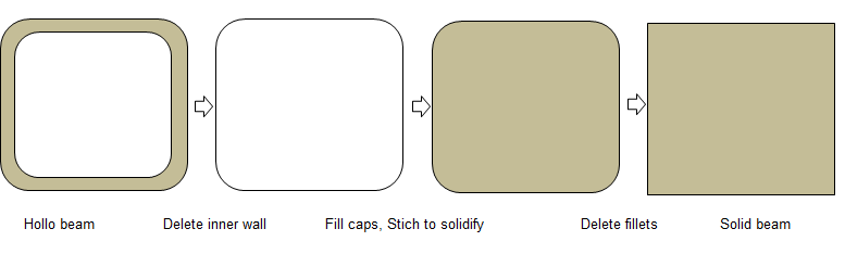
Step-5:
Before removing the wall thicknesss, use the operations appropriate for solids such as Booleans like unite, intersect... to make sure that once converted to surface no further operations such as extend / intersect are needed to remove the gaps / connect the surfaces. Note that this method is not recommended for FEA simulation. In CFD the blockage of flow is important where as in FEA the location of centroid is important. 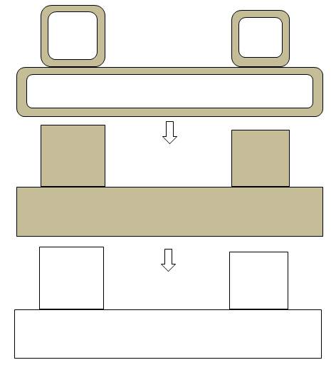
Step-6:
ANSYS Spaceclaim is a CAD-type pre-processor and works better on solids. CFD volume extraction is analogous to 'negative' of visible solid volumes. Instead of deleting the unwanted surfaces one-by-one, it is recommended and worth trying to create a "bounding box" enclosing the geometry and use a boolean to subtract the solids from the 'bounding' box. The resultant negative volume of fluid domain is easy to operate and remove the protrusions generated due to gaps in original (input) geometry.Optionally, re-orient the model so that "Front View" is aligned as per the coordinate system for Front View defined in pre-processor. There is no unique definition of Front View. Some programs define XY-plane as front view, some as YZ-plane.
SpaceClaim Operations
SpaceClaim is a non-parametric CAD program. That means, it does not maintain any hisotry of operations and neither get constraints by one operation from another (except geometrical sanity). ANSYS is adding meshing capabilities also into it and various features can be turned ON or OFF by options shown below:File ↠ SpaceClaim Options ↠ Customize ↠ Ribbon Tabs
Selection
In many pre-processors such as Spaceclaim and ANSA, a box select from left-to-right and right-to-help have different result. The left-to-right box selects only the components which are fully enclosed inside the box. However, the right-to-left box selects every components (solid / surface / curve) whose smallest fraction fall inside the box. SCDM calls is a power selection and a combination of options can be used to select similar features in one go. E.g. All equal radius cylinder, Faces with same area, Holes equal to or smaller than...
Boolean Selection in COMSOL
COMSOL has feature to select entities based on Booleans such as Union, Difference, Intersection and Complement. There is also an option of "Adjacent Selection" to select Exterior and Interior Boundaries.
Selection in SCDM
In ANSYS Spaceclaim, holes, protrusions or fillets can be deleted either by 'Delete' key or 'fill (f)' operation. One of the steps in selection is Zoom operation. Window zoom is also known as Rubberband zoom in some program. It refers to creating a virtual rectangle and that area is expanded to full window.
In ANSYS Spaceclaim, almost every command has additional functionality or features under 'Options' tab. For example, 'Fill' operation has 'Multi-patch' functionality under 'Options' for 'Fill' tool.
Similarly, 'Selection' tab generates multiple options such as "All holes having radius < selected hole", "All surfaces having area < selected surface", "All solid bodies".... SCDM and FLUENT Mesher allow selection of curved surfaces of similar radius, smaller than the selected radius, surfaces having similar or lesser areas.... This is specially useful to remove small fillets in one go. The selection operations only on visible bodies. Switch on "Search All Bodies" to apply the selection to all visible bodies.
All the booleans such as Unite, Subtract, Add and Intersection are built into 'Combine' operations with settings in 'Options'. By default, 'Combine' is a cut operation which may sound counter-intuitive.
To split a body by a non-planar face or a sheet metal body, create the surface which extends beyond the body to be split. If you are not able to pull a surface or pull the edge to make it bigger, copy the surface and then pull that surface into a solid (set option Add for pull operation). This will fill any gap creating pull operation to fail as well as can be used to remove fillets.
Fill operation in SCDM requires a closed volume, that is if the selected surfaces should form a closed volume. This operation replaces the selected surfaces with neighbouring surfaces by extending them as required. Hence, sometimes a surface which is part of the volume to be removed / filled needs to be split appropriately. A subset of fill is "Remove ➔ Rounds" under prepare tab. Only round surfaces get selected when this option is ON". The "Remove ➔ Rounds" can be used to split the fillets and then delete them segments easily. If one needs to fill large number of protrusions each formed by 2 or more surfaces of different areas, create Named Selection for each value of face area using Smart Selection. Then select desired surfaces using the Named Selections. Use fill command to remove protrusions.
When you are not able to fill two adjacent surfaces, very likely there is a sliver surface step looking like an (extra) edge on the surface.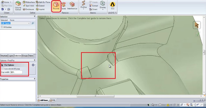
Blend operation need not be between two lines only. It can be used to create a volume by selecting two surfaces.
Sometimes, a fill or blend operation may not work when few surfaces are missing to convert a volume into 'solid' body. One option is to use "Missing Faces" which has options to create a patch with "Multiple Faces". Most often than not, this is a better option than manually filling the missing surfaces.
When features do not get filled or removed from a solid body (such as non-manifold surfaces), the only option is to manually delete those surfaces and then stitch them again. Note that the moment any surface is deleted, the solid body will transform into a surface body.
It is recommended to use Split Edges under 'Fix' tab to merge edges. Note that it is "Fix Split Edges" and not "Split Edges". Also, the features to remove small edges and small faces should be used before importing it to pre-processor such as FLUENT Mesher.
Read the help text carefully. E.g. the Volume Extract operation prompts user to select the 'Bounding' faces and hence one should never select a surface which is expected to be one of the surfaces of the extracted volume.
When the geometry consists of mix of 'Transparent' and 'Opaque' bodies, select all and pressing 'Opaque' icon will not make any change in the appearance. Press the 'Opaque' icon twice to make everything appear 'Opaque'.
ANSYS Spaceclaim has following options to repair geometry problems:
- Solidify
- Stitch Adjacent Faces - if the surfaces form a closed volume, it will result in a solid body.
- Repair Gaps
- Find and Correct Missing Faces
- Fix Curves
- Repair Split Edges - the edges of a surface which were divided into many segments for some reason shall get merged into single curve.
- Extra Edges - removing extra edges are equivalent of merging faces. The edges at the common boundaries of tangent faces or nearly tangent faces are removed.
- Duplicates
- Fix
- Fit Curves
- Curve Gaps
- Duplicate Curves
- Small Curves
- Holes: these are through holes for bolts and blind holes for dowel pins or manufacturing purposes.
- Small features: when fillets (also known as blends) are applied at corners, the small surfaces get generated resulting in very small edges as well. Some times such features are also called 'sliver' which literally means fragments or chip.
- Intersecting geometries: as the name suggest, this refers to the surfaces penetrating or piercing each other without any split at the line of intersection.
- Open boundaries: boundaries creating leaks in geometry, Free edges: edges not connected to any surface
- Intersecting zero thickness walls: a wall with fluid on both sides, may be desirables features at time
- Close proximities: surfaces close to each other creating what is called 'gaps'
- Duplicate nodes: two nodes with the same Cartesian coordinates. This is not permitted by most mesh generation algorithms.
- Fillets, Chamfers and Material Thicknesses: Zero thickness walls and baffles: baffles are zero thickness walls with the same fluid or solid zone on both sides. Interior walls have different fluid and / or solid zones on both sides of the wall. In FLUENT Mesher: Volumetric Regions ➔ Right Click ➔ External Baffles ➔ Draw can be used to draw and check baffles
- Self-face Proximity, Self-edge Proximity:: sharp corners, trailing edge of an aerofoil, tyre on a flat surface, thickness of fins.
Pre-processing: FLUENT Mesher
The first operation one needs to perform on the mesh after importing a CAD geometry as surface mesh is to get rid of 'sliver' faces. It can be accessed through 'Diagnostics' or through TUI in FLUENT Mesher.The second operation is to merge the nodes within some threshold. If you have imported the surface mesh with minimum size set to 1.0 [mm], all the nodes within 0.25 [mm] or even 0.50 [mm] can be merged. This happens when the surfaces do not share common edge such as when there is a gap.
However, in case mesh for thin sheets, merging nodes with relative tolerance may lead to non-manifold vertices - the nodes on one face of the sheet may merge with nodes on the other face of the sheet. E.g. the thickness of sheet is 2 [mm] and surface mesh size is 5 [mm], the "Node Merge" operation with relative tolerance of 50% may lead to merging of node separated by 2.5 [mm].
Toolbars
Out of all the icons, the 'Set' (icon of a circle with 5 dots) and 'Position' (Cartesian coordinate system icon) are used in conjunction with other operations such as 'Project', 'Move To'...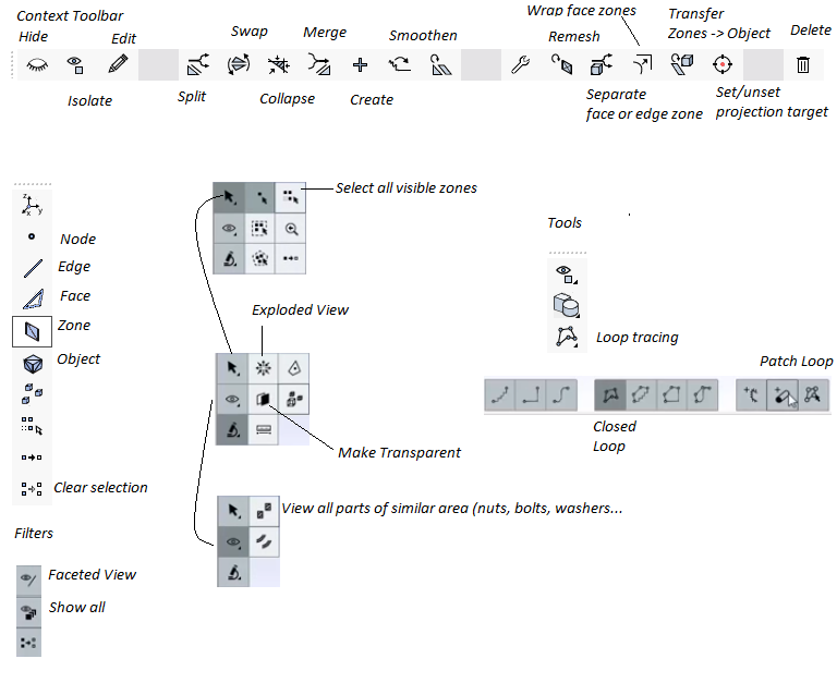
In ANSYS FLUENT Mesher, the keyboard short-cuts works in pair / sequence. That is, one key operation will lead to many other operations - e.g. ^C = colour selection mode. This activates other options namely ^z for "Colour by zone", ^o for "Colour by object", ^p to "Toggle colour palette and ^r to "Randomize colour". From my experience, I find it worth only those short-cuts which can be operated with left hand alone. Since one's right hand is always on mouse, short cuts requiring both hands are not ergonomic. This makes only 12 characters (4 x 3 rows) easy to operate along with control and control + shift keys combinations.
FLUENT meshing mode has options to select entities based on type. The sub-windows has tab such as FaceZone Groups [0/25], Cell Zone Groups [0/3], Edge Zone Groups [0/2] and Node Zone Groups [0/2] - each containing multiple options to select entities based on type. Cell Zone Group has 3 options: dead, fluid, solid. Face Zone Group has many options: boundary, far-field, geometry, inlet, interface, interior, jump, mixed, outlet, overset, periodic, ply, quad, symmetry, tri, wall, wrapper. By clicking (selecting) inlet you can select all boundaries defined as type inlet (pressure inlet or velocity inlet or mass flow inlet). If no boundary zone gets selected, no boundary of type 'inlet' is defined in the mesh.- Selection: picking the elements is one of the most important operations in dealing with meshes. Mouse click the the most basic form of selection. In FM, RMB (right mouse button) is used to select elements (nodes, edges, faces) and zones / bodies. There is a distinction in 'Selection' and 'Marking' of elements.
- Mark element(s) Cntr + J Cntr + s = mark selected faces, Cntr + d = select cells by flood-filling, Cntr + r = add ring of elements around selected cell (default 3 elements), Cntr + g = mark faces by feature angle Cntr + u = unmark all cells
- Select an element Cntr + S = separates face zone or edge zone
- F4: toggle between mouse select and polygon selection
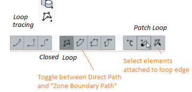
- Loop selection: "Direct Path" - a straight line is added between two selected nodes, "Node Loop Closing Path" - the connecting line is the shortest path tracing along the edges of the cells and "Zone Boundary Path" - the connecting line between two nodes follow the boundary (edge) of the surface.
- Loop select an edge Cntr + j = select all the nodes on that loop. The selected nodes can be further used to project and / or translate the nodes.
- ^n = node selection mode, ^e = edge selection mode, ^f = face selection mode and ^z = zone selection mode
- Conditional display mode: Ctrl + shift + d followed by either of following shortcuts --- ^s = isolate similar surface area, ^c = isolate similar surface curvature, ^n: isolate with neighbourhood, ^+shift+a ≡ ^A: show all, F2: exit conditional display mode
- User Defined Groups: Group creation is a useful tool for meshes with large numbers of boundaries so we can select/deselect them quickly. Select Face Zones for the group from the list and hit 'Create'. The name given will appear as a filter under "Face Zone Groups" in forms throughout Fluent Meshing.
- Visualization: one basic requirement is to see through the surfaces. Clipping or section or cutting planes are invariably present in all pre-processors. Clipping planes can be used to check free edges, overlaps...
- Merge: this refers to the process of combining two entities (objects, walls, edges, nodes). Geometry objects can be merged using the Merge Objects option. Wall face zones comprising objects can be merged using the Merge Walls option. The first node selected is retained and the second node is merged onto the first node. Always merge nodes first before stitching. In FLUENT Mesher, merge nodes by increasing the tolerance in steps of relative percent of 10% till 50% is reached (up to 90% can be tried though).
- Intersect: a boolean operation that keeps only the 'common' feature. This operation is primarily used for surfaces which are inclined to each other. All zones with the distance between them ≤ specified tolerance value shall be intersected. Increasing the intersect tolerance to high value such as 2.5 may yield unwanted results such as mesh jumps, non-manifold vertices... It is recommended to use 'Project' operation before intersect.
Steps are as follows: select the target plane (horizontal plane in this case), press 'Set' icon or ^s (note small 's'), select the edges (or nodes) to be projected (horizontal edge of vertical plane), use shortcut key ^p (note small p) or Boundary ➔ Modify ➔ Project.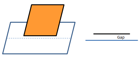
To make this operation easy to execute, one need to create suitable Face Zone Labels so that only required face zones are displayed on the screen. Use 'Split' operation and rename the default labels generated by this operation.
For 'Intersect' operations, keep the 'Separate' options ON. It will create separate zones for unwanted faces. - Split (F7): similar to intersect but does not retains all the feature. During splitting, the selected cell will be refined by the addition of a node at the centroid of the cell. Each triangular face will be split into three faces by adding a node at the centroid. Each quadrilateral face will be split into two triangular faces. To split boundary zones into two different zones: select one element > activate zone selection mode > activate edge zone selection filter > select edge zone defining the boundary > click separate zone icon.
- Join: operation required to make unique face zone from overlapping face zones, similar to stitch but used to remove overlapping surfaces. Stitch works on non-overlapping surfaces. In FLUENT Mesher, overlapping areas of two boundary zones are merged and the mesh at the boundary of the region of overlap is made conformal. To join surfaces that are on top of each other but not connected (with a small gap), the portion of the surfaces within a specified 'tolerance' value will be joined.
Feature Angle specifies the minimum angle between the feature edges that should be preserved during re-triangulation. All the edges in the zone having feature angle greater than the specified Feature Angle are retained. This option is useful for preserving the shape of the intersecting boundary zones. Default value = 40°, a value in the range of 10~50° is recommended. Higher values may distort the shape of the intersecting boundary zones.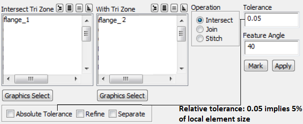
Join, Intersect and Stitch operations are collectively called 'connect' operations.
- In case of completely overlapping zones, one need to separate the zones and join in separate pairs. A TUI command is also available to remesh overlapping zones: /boundary /remesh /remesh-overlapping-zones. If you mark cells based on say skewness > 0.8 and then click on first set of marked cells to Remesh them, click the Remesh tab again to remesh all the marked cells. Of course, one can remesh one by one each group of cells marked so.
- Stitch: required for badly mismatched 'overlapping' nodes and faces. It is a 'sewing' operation where two surfaces are connected with unique edge. The boundaries are retained which is not the case in 'Join' operation.
The 'stitch' option in FLUENT Mesher is used to connect two tri boundary zones along their free edges. It cannot be used to connect the surfaces at a location other than the free edges in the mesh. Gaps within the given tolerance are closed using closest point projection.
Use TUI /boundary/check-duplicate-geom to delete duplicate face zones. - Fill Holes: create a coplanar patch (also called capping surface) from enclosed boundary. In FLUENT Mesher, select an edge of the hole and use "Patch Option" menu '+' or F5. It will automatically create a closed loop traversing the adjacent edges attached to the selected edge. If you select a face, FM will attempt to close all the holes belonging to that surface.
- Create: a new object or geometry feature is added. Alternatively, select few nodes around the hole and press F5 to create the surface that closes the hole. Once an edge loop can be created by selecting nodes through the Loop Selection option, use short-cut key ^k to create the capping object.
- Faceted Stitch: repair surfaces having internal cracks or free edges or poorly mismatched facets. This is different from node merge in that triangles can be split to add nodes. Large tolerances can cause faceted stitch to collapse geometry, especially for STL where lots of triangles have high aspect ratio. Start with low tolerances (such as 0.01) and gradually increase to remove free faces. Always inspect as you increase tolerance to ensure geometry remains valid.
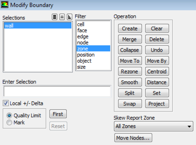
- Collapse (F9): remove a feature by merging two nodes or edges or surfaces. 'Collapse' operation works on concept of centroids. If a triangular face is selected, a new node is created at the centroid of the triangle and the selected triangular face gets deleted.
- 'Collapse' operation for two selected nodes is equivalent to "merge to average".
- Sometimes 'collapse' operation may simply delete the elements and create a void/gap. Verify the topology after every collapse operation especially near T-junctions.
- Multiple pairs of entities can be collapsed simultaneously by selecting them in "ordered pairs" that is they will collapse in the order entities are selected. Thus, [first and second], [third and fourth]... entities shall get collapsed.
- Swap (F8): interchange the topology connectivity.
- Smooth: change the topology closest to the ideal shape. A node is placed at a position computed from the average of the surrounding nodes.
- Project (^p): project a node on an edge or surface, project edges of an edge loop onto a face zone. Eg. in FLUENT Mesher, the "Closest Point" method specifies that the edge should be projected to the closest point on the face zone selected.
- The "Specific Direction" method allows to project the edge on the face zone in a specific direction.
- The 'Project' operation works on principle of minimum perpendicular distance.
- If two nodes are selected, ^s will create a target line of very large length. Thus, all nodes are projected on the nearest perpendicular location on that (extended) line.
- Similarly, when 3 nodes are selected, ^s will set a plane of large dimension.
- Set (^s): set options, views, controls... objects/set/set-edge-feature-angle sets feature angle for /objects/extract-edges command. 'Set' operation (^s) is toggle type. Press ^s again to unset the target.
- Mesh Zone Modifications: operations such as re-zone can be use to move cells which have been incorrectly assigned or move to inappropriate face zone.
- Apply prefixes to zone names: Boundary ➔ Manage ➔ Rename ➔ Change Prefix ➔ Select "Face Zones".
- Move: move a node or an edge - move the selected node either to a specified position or by a specified magnitude. Highly skewed meshes can be improved by moving the nodes of the cells.
- Clear (F2): clear selections, 'marked' zones or faces from some other operation.
- Delete (^w): remove an object or entities from the topology. F12 = undo last operation. Operations which cannot be undone are:
- Delete face zone
- Separate face zones
- Merge face zones
- Remesh elements or zones
- Rezone: move faces, edges and/or nodes to an existing zone or a new zone.
- Centroid (^d): print in the console centroid coordinates of a selected cell. The distance between two nodes, two edges, two faces, an edge and face pair, a node and edge pair... can be reported in graphics window with ^d short-cut.
- Misc. Tool Menu (^t), under miscellaneous tool menu, the path between two entities can be traced by pressing ^t again. That is, select two elements or faces, press ^t twice to trace the path. This operation can be used to trace leakages.
- Rezone Faces: Select the faces yout want to move ➔ Select the zone to which those faces to be moved ➔ Click Rezone icon or ^+Shift+O.
- Face Connectivity: Invalid Normal - Invalid normal are locations where prism quality will be bad, although surface mesh quality is good. Prisms has to be applied on the boundary zones to activate this operation and to find the problem. Fix by smoothing all the nodes surrounding the bad normal.
Periodic Mesh
There are many cases where the overall geometries (computational domains) are too complicated to mesh in single step though they may comprise of sections periodic in nature. For smaller (periodic or symmetric) geometries, it is easier to set local mesh controls (on edges and faces) and carry out trials to get optimal mesh. Once a mesh for periodic volume is generated, it can be copied to fill the entire volume followed by node-merge operations to make the coincident periodic faces conformal internal walls.
Periodic boundary condition in Fluent Mesher is not among standard boundary type. The periodic boundaries can be created in FLUENT Mesher with TUI command: boundary make-periodic. In ANSYS Meshing, the periodic planes should have matching areas, number of edges and number of vertices on the two planes. This video from ANSYS explains the steps required to generate periodic meshes. Note that this method follows water-tight geometry workflow and may not work for Outline approach.Another option to create a translational periodic boundary condition in Fluent mesher is to assign symmetry boundary condition to two periodic patches (say periodic_1 and periodic_2) in FLUENT mesher. Once mesh is imported into FLUENT Pre-post, change the type to interface. Note that boundary layers shall not get generated on zones defined as type 'symmetry'. in ICEM CFD, there is an option in the GUI to define periodicity under Global Mesh Setup.
The mesh generated into a sub-domain and then copied to make full domain results in too many coincident faces. Node merge is not allowed with polyhedral mesh in FLUENT Mesher. One option is to fuse boundaries (and merge duplicate nodes and faces) created by assembling multiple mesh regions in FLUENT Pre-post. However, it would require manual selection of faces to be fused.Remove Gaps between Faces
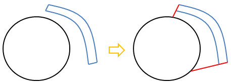
FLUENT Mesher has option to remove the small gaps between surface, both planar and curved faces. The standard approach to remove gap is to delete surface on the one side and then project the edges of that side on the adjacent surface.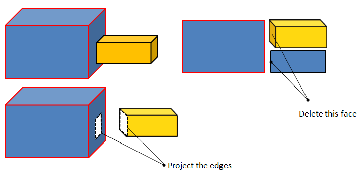
Method to remove gaps between 'Mesh Objects' and not between Face Zones: This method is applicable for removal of gap between two "Mesh Objects". Following steps are needed, note that this operation cannot be undone and hence one need to save the model before this.
Step-1: Set 'Priority' of the neighbouring "Mesh Objects" using "Change Zone Properties" option - the pencil icon.
Step-2: Right click on the "Mesh Object" ❯ Remove Gap ❯ Set 'Parameters' ❯ Gap Type ❯ Order (Priority)
Step-3: Click on 'Mark': no change in graphics window (display of mesh) will occur. Click 'Draw' to show up 'Marked' faces.
Step-4: Click 'Remove'. Click on 'Draw' again to view the modified topology. Use 'Intersect' or 'Join' as deemed appropriate.
Method to remove gaps within 'objects' - between Face Zones: This method is equivalent to Boundary ❯ Zone ❯ Project, note that this operation cannot be undone and hence one need to save the model before this. This is applicable to face zone within a mesh object and can be used on planar as well as non-planar surfaces.
There are 3 projection methods: Normal, (Specified) Direction and Closest. For thin gaps, 'Normal' and 'Closest' are likely to produce similar results.
Boundary ➔ Mesh ➔ Improve: To improve selected zones based on the Quality Measure. Quality Limit specifies the quality limit for the improvement operation. All elements above the specified quality limit will be acted upon.
- Angle: specifies the maximum allowable angle between two adjacent face normals above which smoothing cannot occur
- Iterations: specifies the number of improving attempts
- Preserve Boundary: prevents movement for nodes on edge loops around face zone boundaries.
Very small triangles can be collapsed en masse using "Improve by Area". When using "Min Absolute Size" users should preview their selection using the Size option in the Display Grid panel to view the faces with area below the selected threshold.
Meshing Thin Gaps
Many times, one may need to capture thin gaps to account for leakage or trapped air. In case it is only a trapped air (which acts like conduction layer and no convection), it can be simplified by modeling the gap as contact resistance. In case you must capture gaps which is far too small as compared to overall domain size, it requires special attention and special method. If you decrease minimum cell size so small that the proximity size control is able to get 3 to 6 layers of cells in the gap, this may increase the overall volume mesh count to unreasonably high values. The ideal and sometimes only option to mesh such gaps are sweep meshing where the element size can be 20 to 50 times larger in direction perpendicular to the gap.Another option in ANSYS Meshing is to use hard behaviour. When a hard behaviour is specified, AM tries to respect the prescribed element mesh size (and/or number of divisions for the edge meshing) on that entity. Hard behaviour is useful to refine the mesh and use element sizes that are smaller than the default size. Though, this approach does not ensure desired number of volume elements across the gap throughout the gap.
Yet another option is to mesh the thin gap portion of the model with a different method (such as ICEM CFD blocking) or sweep meshing in ANSYS Mesher, then merge it with the rest of the model, either with conformal or non-conformal interfaces. The method to assemble meshes in Workbench is explained here. The sweep option in AM impose following conditions of geometry: "A sweepable body must have the same topology (lenths of edges and number of vertices) of faces on the source and target sides, and the swept (side) faces must not have any extra splits or faces."
Excerpts from ANSYS Meshing User Guide: "The MultiZone mesh method provides automatic decomposition of geometry into mapped (sweepable) regions and free regions. When the MultiZone mesh method is selected, all regions are meshed with a pure hexahedral mesh if possible. To handle cases in which a pure hex mesh will not be possible, you can adjust your settings so that a swept mesh will be generated in structured regions and a free mesh will be generated in unstructured regions."
Excerpts from FLUENT Meshing User Guide: "Thin Volume Mesh creates sweep-like mesh for a body occupying a thin gap. You define boundary face zones for source and target such that the source face normal should point to the target. The source face mesh may be triangles or quads. Four other controls are then used by Fluent Meshing to grow the volume mesh from the source zone to the target zone." The mesh generated by this approach is stored under "Cell Zones" tab in Unreferenced section of the model tree. One can proceed with normal Auto Mesh operation when all "Thin Volume Mesh" generation are complete.
Hints on Volume Mesh Size
In Fluent meshing, the smaller size takes priority irrespective of whether it is due to global sizing or local sizing. Local sizing gives control over meshing specific entities chosen by the user. For all other surfaces, global size control shall get applied. Thus, local size controls are intended to refine the mesh and global size controls for obtaining coarse mesh in rest of the volume. TUI command /boundary/edge-limits prints the length of the shortest and longest edges on the boundaries. This information is useful for setting initial mesh parameters and refinement controls.- It is strongly recommended to have surface mesh quality (skewness) < 0.6. Max tri skewness should aim to be ≤ 0.8 to get a good quality tet mesh with tet skewness ≤ 0.9.
- The further the skewness of triangle mesh, the better the quality of the tetra mesh . E.g. Maximum skewnes ≤ 0.5 would give excellent tetra quality ≤ 0.8 skewness and generally very good solver convergence
- At growth rate = 1.2, the number of cells in volume mesh would be in the range 4 ~ 8 times the number of surface mesh, without any prism layer.
- At growth rate = 2.0, the number of cells in volume mesh would be in the range 3 ~ 5 times the number of surface mesh, without any prism layer.
- The number of prism elements = number of surface mesh x number of layers.
- At growth rate = 1.2, the number of cells in volume mesh would be (n + 4 ~ 8) times the number of surface mesh where 'n' is number of prism layers.
- On a 32 GB RAM machine, it is difficult to operate on case and data files generated on a mesh with more than 40 million cells.
- On a 128 GB RAM machine, it is difficult to operate on case and data files generated on a mesh with more than 100 million cells.
Mesh Generation in FLUENT Mesher
![]()
There is no CAD Kernel and Fluent Meshing (FM) is a fully faceted meshing tool. If CAD is imported it is tessellated on import. ANSA, Hypermesh, COMSOL, STAR-CCM+ have CAD Kernels and they can import geometry as CAD objects and export geometry to neutral CAD formats such as STEP and IGES. Face Zone Labels must start with an alphabet else FLUENT Mesher shall add prefix 'zone'. Face zone labels in FLUENT Meshing are created as "component name" + - + "body name".
Notes:
- FLUENT recognizes '-' or hyphen in names, CFX does not and converts '-' into white space.
- FLUENT mesher cannot save mesh in 2D formats say for 2D simulations in FLUENT. Though, it can read 2D-surfaces and 2D-mesh.
- Material point and Face Zone Label should not be same else mesher will add a numeric suffix to the volume mesh
- Volumetric Region and Mesh Zones can have same names
- FLUENT Mesher refers to ZERO thickness walls as 'Baffles' and the number of baffles are printed after Compute Volume operation
- To create a patch, one does not need to split the patch. Select elements and create patch. One a patch is created, it is better to merge it with neighbouring surfaces to manage the large number of zones. If the newly created patches are meant for any specific boundary type, they need not be merged.
- Switch OFF mesh edge display mode to improve graphics response.
- In FLUENT Mesher, domain extension can be created through the feature Main Menu ➔ Boundary ➔ Create ➔ Swept Surface: user needs to select the boundary name and "sweeping operation" shall automatically pick the edge or boundary of that face zone. Main Menu ➔ Boundary ➔ Create ➔ Plane Surface can be used to create a cutting plane for symmetry boundaries or plug a hole before wrapping.
- objects/set/set-edge-feature-angle sets feature angle for /objects/extract-edges command.
- Location of free edges are not necessarily the location of leaks. After every major 'delete' operation, it is recommended to compute volume.
- If there are self-intersection, self-proximity or duplicate elements, "Compute Volume" operation may fail and FM may stop working.
- Boundary elements with skewness 0.5 ~ 0.7 represents elements with high aspect ratios. Use the 'Sliver' diagnostics to collapse them.
- FLUENT Mesher keeps selection unless deselected explicitly. Hence, every delete, merge, separate... operations, use Deselect All operation before selection. 'Isolate' followed by Fit to Window operation is another handy way to make sure only intended zones are covered in operations.
- Do not merge zones until a surface mesh of desired quality is achieved and all boundaries are appropriately defined and named.
- There is no GUI operation to find area of a zone. Use /report/face-zone-area zoneName to find out area of the 'zoneName'.
- Once you compute "Volumetric Regions", use TUI /objects/volumetric-regions list objectName * () to print a tabulated information of all volumes printed under headings "name | type | volume | material-point | face-zones"
- Create Material Points: material-point create-material-point zone_name xmp ymp zmp - note that it does not check if the specified points fall within the domain or not.
- Some useful TUI commands where wild-card character * can be used to access zones containing specific characters.
- /report/summary yes mesh_summary.out
- /object/list, mesh domains print - prints summary of domains and number of edge / face / cell zones in each domain.
- boundary manage list - prints a summary with zone ID, name, type and number of triangle / quad elements. Go to Checklist
- /boundary/manage/remove-suffix: removes the suffix which is characters including and after the leftmost ":" character in the face zone names.
- /report/face-zone-area (ex*) or to get zone having minimum area: (tgapi-util-get-minsize-face-zone-by-area "*")
- /mesh/modify-zones/list-zones
- /mesh/modify-zones/merge-zones zoneX zone1 zone2 ...
- /mesh/modify-zones/zone-name oldZone newZone
- /report/face-zone-at-location, report/cell-zone-at-location
- /mesh/modify-zones/zone-type x
- /boundary/compute-bounding-box: get extents of the computational domain
- /boundary/slit-boundary-face: two-sided wall conditions for the boundaries needs to be split into two virtual overlapping zones.
Zone type 'x' in FLUENT are [velocity-inlet, pressure-inet, mass-flow-inlet, inlet-vent, intake-fan], [mass-flow-outlet, pressure-outlet, outlet-vent, outflow, exhaust-fan], [axis, symmetry, interface, overset, pressure-farfield, wall].
SCHEME script to generate volume mesh in batch mode say on HPC cluster
;Read the surface mesh
/file/read-mesh surfaceMesh.msh
;
;Optionally, compute volume regions - better do in GUI mode
;/objects/volume-regions compute objectName useMaterialPoint?
;/objects/volume-regions compute simRegion yes
;
;Set auto-mesh paramters as per syntax below
;/mesh/auto-mesh objectName keepSolidZones? quadTetTransion volumeFill mergeCellZones?
;/mesh/auto-mesh fluid yes pyramids tet yes
;/mesh/auto-mesh simGeom yes pyramids poly yes
;/mesh/auto-mesh fluid yes pyramids hexcore yes
;
;Save raw volume mesh with quality as generated
/file/write-mesh volumeMeshRaw.msh
;
;Clean-up mesh zone names
/mesh/zone-names-clean-up yes
;
;Improve mesh quality: skewness
/report/quality-method/skewness angle
/mesh/modify/auto-node-move (*) (*) 0.99 50 120 yes 5
/mesh/modify/auto-node-move (*) (*) 0.98 50 120 yes 5
/mesh/modify/auto-node-move (*) (*) 0.97 50 120 yes 5
/mesh/modify/auto-node-move (*) (*) 0.96 50 120 yes 5
/mesh/modify/auto-node-move (*) (*) 0.95 50 120 yes 5
/mesh/modify/auto-node-move (*) (*) 0.90 50 120 yes 5
;
/file/write-mesh volumeMeshFinal.msh yes
/exit yes
Import Mesh or CAD Geometry:
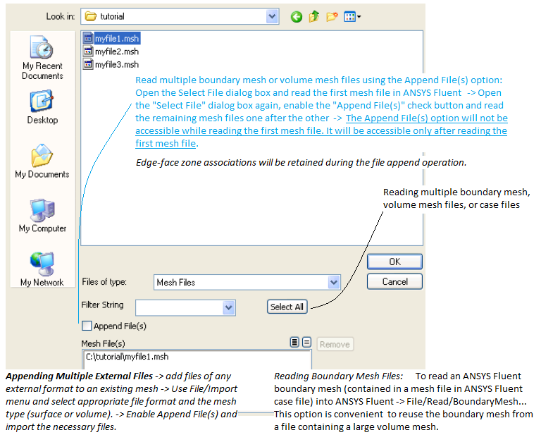
It is easier to generate mesh and improve quality on the smaller geometries. Hence, it is recommended to generate the surface mesh of independent sections of the computational domain and merge/combine later. The mesh quality and number of cells can be easily operated and managed on smaller domains than the entire domain. Note:
- In FLUENT Mesher or any other pre-processor, the component and body name defined in Spaceclaim or CAD program may be split into large number of mesh objects.
- It is recommended to merge the "Mesh Object Labels" in to manageable numbers. This helps viewing and using diagonostics on a smaller segments out of large surfaces area, shape and size.
- Renaming and merging "Mesh Object Labels" do not change the internal structures of zones created in FLUENT Mesher during CAD import. The objects should be 'merged' using option Boundary ➔ Modify ➔ Merge.
- View the "Mesh Objects" one-by-one, use diagnostics to remove (collapse / delete)'sliver' elements.
TUI commands on importing CAD geometry
- /file/import/cad - allows you to set the basic options for importing CAD files.
- /file/import/cad-options/continue-on-error? - allows you to continue the import of the CAD file(s), despite errors or problems creating the faceting on certain surfaces or other issues. This option is disabled by default.
- /file/import/cad-options/enclosure-symm-processing? - allows processing of enclosure and symmetry named selections during import. This option is disabled by default. This option is applicable only to ANSYS DesignModeler (*.agdb) files.
- /file/import/cad-options/use-component-names? This option is enabled by default, use component names in Discovery as Object names in FLUENT Meshing.
- /file/import/cad-options/import-body-names? - allows import of Body names from the CAD file(s). This option is enabled by default. If set 'no', face zone labels are names as region1, region2... where integer suffixes are not continuous numbers.
- /file/import/cad-options/import-part-names? - import of Part names from the CAD file(s). This option is enabled by default.
- /file/import/cad-options/named-selections - import Named Selections from the CAD file(s), including Named Selections from ANSYS DesignModeler.
- /file/import/cad-options/one-object-per - allows you to create one object per body/part/file to be imported. When you choose to import one object per body, you can optionally choose to create one zone per CAD face imported.
- /file/import/cad-options/read-all-cad-in-subdirectories? - disabled by default. If enabled, all files in the specified directory as well as in its subdirectories will be imported.
- /file/import/cad-options/recover-missing-faces? - recreate missing face tessellations during the file import.
Working Example of Meshing in Batch Mode
Basic Import Options:
/file/import/cad-options/one-object-per part
/file/import/cad-options/modify-all-duplicate-names? yes
/file/import/cad-options/name-separator-character '_'
;Add specified label to names of double-connected face zones (shared by 2 bodies)
/file/import/cad-options/double-connected-face-label 'iface-'
Import CAD in Empty File - this import geometry as CAD Objects: /file/import/cad yes fluid_geo.scdoc yes 40 yes mm
Explanation: Import single file [yes] yes, CAD Import File Path [""] fluid_geo.scdoc, Extract Features [yes] yes, Feature angle(deg) [40] 40, Import Curvature Data from CAD [yes] yes, Length unit [mm]> mm
Re-import without appending: /file/import/cad yes fluid_geo.scdoc no yes 40 yes mm ok. Here last prompt 'ok' is for: Any unsaved data will be lost. Do you want to proceed? [ok]
Import as Mesh Object
First time import: /file/import/cad-geom yes fluid_geo.scdoc mm cfd-surface-mesh no 2.5 10 1.25 yes yes 5 2 faces-and- edges yes no
Re-import by replacing existing mesh: /file/import/cad-geom yes fluid_geo.scdoc no mm cfd-surface-mesh no 2.5 10 1.25 yes yes 5 2 faces-and-edges yes no ok
Explanation: Import single file [yes] yes, CAD Import File Path [""] fluid_geo.scdoc, Length unit [mm]> mm, Tessellation Method [cad-faceting]> cfd-surface-mesh, Use size field file? [no] no, Minsize [0] 2.5, Maxsize [0] 16, Growth-rate [1.2] 1.25, Enable size function: Curvature? [yes] yes, Enable size function: Proximity? [no] yes, Curvature Normal Angle(deg) [10] 5, Cells per gap [3] 2, Scope proximity to [edges]> faces-and-edges, Auto-Create Scoped Sizing? yes, Save size field? no, Any unsaved data will be lost. Do you want to proceed? ok
Minor Mesh Improvements
/diagnostics/face-connectivity/fix-free-faces/merge-nodes, /diagnostics/face-connectivity/fix-free-faces/merge-nodes stitchHole Repair Steps: note that the operations corresponding to 'Wrench' icon have been merged into other operations and this icon is no more present in V19 onwards.
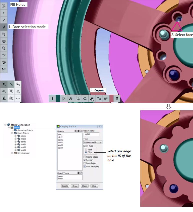
Proximity Checks: This feature is used to find gaps and acute angles within an object. In input geometry, a fillet should be created to avoid the problem. Use this option with caution since the boundary of the mesh can be very uneven and faces may collapse.
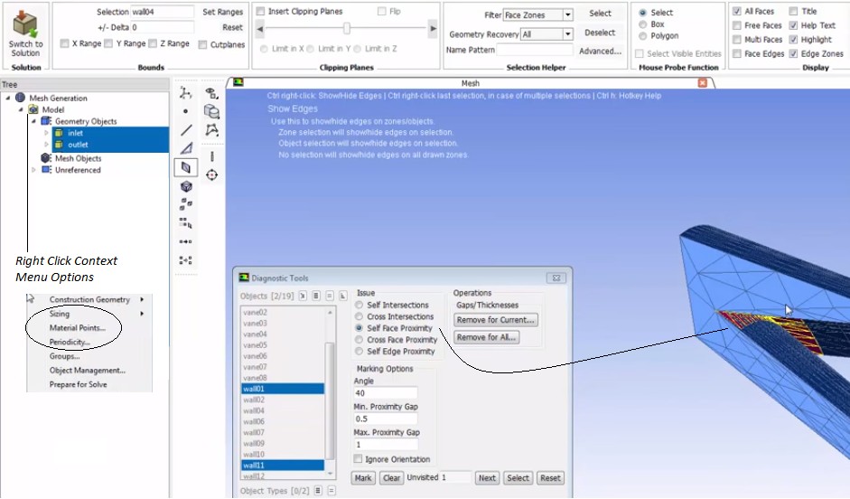
It is recommended to correct the geometry to eliminate proximity issues. In Ansys SpaceClaim, the method to handle proximity issues are explained here.
A 'gap' is defined in one of two ways: area between two opposing boundary edges of a face and the internal volumetric region between two faces. The proximity size function sets the minimum number of element layers created in regions that constitute 'gaps'. Gap is not just the two walls defining a narrow fluid zone but also two surfaces defining a thin baffle or plate. Proximity - ON/OFF Surface Orientation - if "Ignore orientation" is ON, surface mesh is not refined along the groove length, where groove is the gap between the adjacent (close) surfaces.
Closing gaps using zone projection: Change to zone filter (Ctrl+z) ➔ Select (generally) the bigger zone and set as the target (Ctrl+s) ➔ Select the smaller zone and project to target (Ctrl+p) . This will close the gap. Additionally one can use Ctrl+k hot key to open the remove gaps panel.
Global vs. Local Join and Intersect Operation
Global Join operations: Change Operation to Join ➔ Select all Face Zone Labels ➔ Click on "Find Pairs" to see that there is a reasonable number of pairs ➔ Click on Join.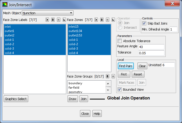
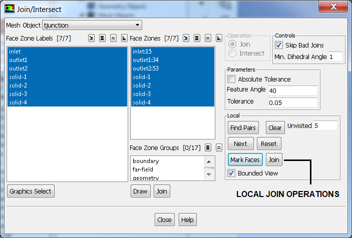
Global Intersect operations: Change Operation to Intersect ➔ Select all Face Zone Labels ➔ Click on "Find Pairs" to see that there is a reasonable number of pairs ➔ Click on Intersect.
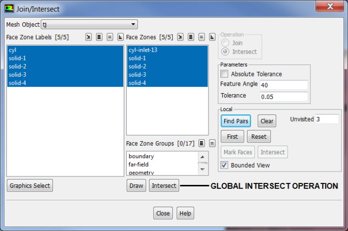
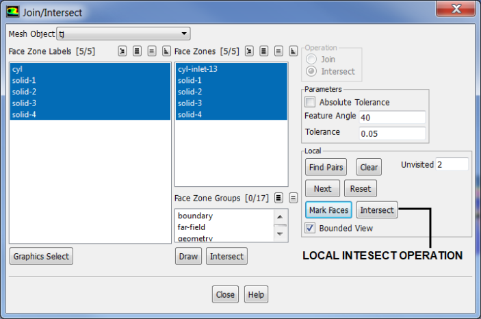
Refine Boundary Zones based on Proximity
Boundary ❱ Mesh ❯ [Refinement group box] ➜ Select the zone from which proximity is to be defined, specify relative distance and click Apply.Remeshing Boundary Zones: To regenerate surface mesh on particular face zones, follow the operation Boundary ❱ Mesh ❱ Remesh ... Surface Triangulation. This operation is required to refine or coarsen few boundary patches only. Follow the following steps:
- Create edge zones of the boundary of the face zones to be remeshed, if not already present
- Modify node spacing on edge zones as needed
- Select "Size Filed" to enable Use Conformal Remesh to select multiple face zones for mesh. FM will prompt to compute the size field or read from a file.
- A TUI command is also available to remesh overlapping zones: /boundary /remesh /remesh-overlapping-zones
Leak Detection
In most of the pre-processors, there is a feature to detect leakages such as open boundaries. ANSYS FLUENT Mesher has "Find Hole" feature under Wrapping operation though it may not yield the leakage path always and remains a bit less user-friendly in showing the leakage path. Leakages are one of the most frequently occurring issues while dealing with assemblies. One way to check the presence of leak is to check number of expected volumetric regions with that computed. FLUENT TUI "objects volumetric-regions list * * ()" shall print all the regions, their type (dead - not to be meshed, solid or fluid), material points... TUI "objects volumetric-regions change-type meshObjName volRegion1 volRegion2 () solid" can be used to change type of these regions.
Another option (inline with the algorithm used in Wrapping process) is to use "Split and Compute Volume" method. For example, the domain can be split into 4 quadrant and 4 material points defined for each quadrant. It is likely that the leakage is found in all 4 quadrants (though the probability is low) unless the geometry has not be checked and reviewed before importing into the pre-processor. The process can be repeated though the split can be into just two halves after initial split into 4 quadrants.
One may even start with just two halves and continue the process till the region having hole(s) is identified.
Import solids only: another approach to minimize likelihood of leakage is to import only solid volumes (note the attribute 'solid' here denotes a closed water-tight 3D volume) into FLUENT mesher one by one and intersect / join later.
Mesh Diagnostics
Once mesh is generated, one case use following recursive TUI commands thorough a journal file to automatically improve the suface mesh globally. Note wildcard character * can be used to include all objects. Since it refers to a list, it has to be used inside parentheses i.e. (*). If one wants to include objects starting only with 'srf', use (srf*) instead of (*). Here, 40 refers to the feature angle, 30 is the number of iterations and 'yes' instructs to preserve boundaries.
| diagnostics quality general-improve objects (*) skewness 0.95 40 30 yes |
| diagnostics quality general-improve objects (*) skewness 0.90 40 30 yes |
| diagnostics quality general-improve objects (*) skewness 0.85 40 30 yes |
| diagnostics quality general-improve objects (*) skewness 0.80 40 30 yes |
When general-improve does not work, the elements can be collapsed using following TUI commands recursively using a journal file. However, before collapsing these skewed elements, one should check that it will not cause distortion in geometry. Face quality in FM refers to skewness and one should not collapse the faces with skewness ≤ 0.7 - this may distort the geometry. If collapse operation creates significant change in shape of the geometry, only option left is to re-mesh those regions.
| diagnostics quality collapse objects (*) skewness 0.990 40 30 no |
| diagnostics quality collapse objects (*) skewness 0.985 40 30 no |
| diagnostics quality collapse objects (*) skewness 0.980 40 30 no |
| diagnostics quality collapse objects (*) skewness 0.975 40 30 no |
Other face connectivity improvement options are:
| diagnostics face-connectivity fix-free-faces face-zones (list 'front 'rear 'top 'bottom) stitch 0.01 1 |
| diagnostics face-connectivity fix-self-intersections face-zones (list 'front 'rear 'top 'bottom) |
| diagnostics face-connectivity fix-duplicate-faces face-zones (list 'front 'rear 'top 'bottom) |
| diagnostics face-connectivity fix-spikes face-zones (list 'front 'rear 'top 'bottom) 100 |
| diagnostics face-connectivity fix-islands face-zones (list 'front 'rear 'top 'bottom) 10 |
| diagnostics face-connectivity fix-slivers face-zones (list 'front 'rear 'top 'bottom) 0 0.75 |
| diagnostics face-connectivity fix-point-contacts face-zones (list 'front 'rear 'top 'bottom) |
| diagnostics face-connectivity fix-invalid-normals face-zones (list 'front 'rear 'top 'bottom) |
| diagnostics face-connectivity fix-multi-faces face-zones (list 'front 'rear 'top 'bottom) all-above 5 20 20 |
Display ➔ Plot ➔ Cell Distribution: Plot or print distribution of cells in a given range of quality (Skewness, Aspect Ratio...). Mesh ➔ Tools ➔ Cell Modify ➔ Click on 'Skew': Display cells (faces and nodes of a tetrahedron) with worst quality
Query Functions
Query functions are a way to probe into the mesh and get the deisired information quickly.- (get-object-of-type 'mesh): list of all mesh objects
- (get-regions-of-object 'meshObjName): list of all volumetric regions of mesh object 'meshObjName'
- (get-face-zone-at-location '(x y z)) - Returns the face zone at or closest to the specified location
- (get-cell-zone-at-location '(x y z)) - Returns the cell zone at or closest to the specified location
- (get-zones-of-type 'type) - Returns a list of zones of the specified default zone type (type ). E.g. (get-zones-of-type 'symmetry), (get-zones-of-type 'boundary-edge), (get-zones-of-type 'fluid)
- (get-face-zones-of-filter 'filter) - Returns a list of the face zones whose names contain the specified filter string. E.g. (get-face-zones-of-filter '*flux*)
Recursive Local Remeshing Script: Following scheme loops mark and remesh faces and neighbours with skewness ≥ 0.5 and is applied to all face zones inside objects containing wildcard *wrap. Works in FLUENT Mesher only.
(define-new-marked-count 0)
(ti-mark-bad-quality-faces) (*wrap) 0.5 0
(set! new-marked-count ( ti-count-marked-faces)) (*wrap)
(if (> new-marked-count 0)
 (ti-menu-load-string "( ti-local-remesh-marked-faces) (*wrap) geo 3 20")
)
(ti-mark-bad-quality-faces) (*wrap) 0.5 0
(set! new-marked-count ( ti-count-marked-faces)) (*wrap)
(if (> new-marked-count 0)
 (ti-menu-load-string "( ti-local-remesh-marked-faces) (*wrap) geo 3 20")
)
(ti-mark-bad-quality-faces) (*wrap) 0.5 0
(set! new-marked-count ( ti-count-marked-faces)) (*wrap)
(if (> new-marked-count 0)
 (ti-menu-load-string "( ti-local-remesh-marked-faces) (*wrap) geo 3 20")
)
Wrapping
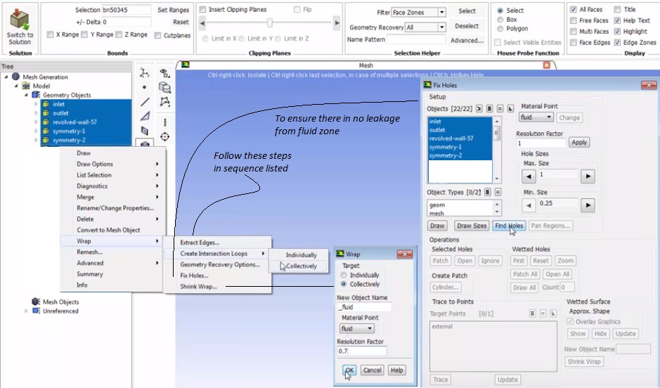
Import of geometry as "CAD Faceting" is recommended for large model and for geometries intended to be wrapped. 'Tolerance' of CAD faceting is the minimum facet size which should be ~ 1/10 of minimum CFD surface mesh size.
Wrapping process in FLUENT Mesher is described below. The dimensions of the geometry discontinuity such as holes, gaps in the input geometry should be smaller than that of the size of the Cartesian cells created by the wrapper. If there are larger distortion in the input geometry, repair it to the extent that the distortion becomes smaller in size.Large holes, if present in the initial geometry, should be filled else such holes will be ignored in the wrapping process. Gaps in the geometry larger than the local element size are called "Fully Resolved Gaps".
- A coarse Cartesian grid is overlaid on the input geometry (including gaps and overlaps). This Cartesian grid is used to automatically clean the input geometry and to create the water-tight representation
- Colour code: non-intersecting hexahedrons (Cartesian cells not intersecting with model geometry - edge / faces) are coloured white, intersecting cells are shown in dark blue
- The intersection between the Cartesian grid and the input geometry is calculated and the intersecting cells are identified and marked
- A watertight faceted representation is created along the boundary of the intersecting cells
- The nodes on this faceted representation are projected on to the faces and feature edges of the input geometry which then results in a wrapper surface closely representing the input geometry
- The wrapper surface quality is improved by post-wrapping operations such as smoothing, swapping...
The Min Length is the minimum allowable cell length in the Cartesian grid. A smaller size captures details more accurately and also reduces the crossover configurations, although it increases the number of holes in the geometry. Hence, it is recommended to specify a Min Length value < half the required mesh size. Further, specify Min Length value 3-4 times smaller than the size of important narrow gaps present in the domain.
The Pan Regions dialogue box allows you to observe and analyse the region (to be wrapped) created during the Cartesian grid initialization. When the plane passes through the Cartesian grid the interior of the Cartesian grid is displayed at every position on the plane. If at any position of the plane the color of the region is seen inside the geometry, there may be a leak or hole in the Cartesian grid. The Pan Regions dialogue box only allows to know whether or not there is a leak or hole in the geometry and it does not tell the exact location of the leak.
One may not get the best wrapping in first step. Once an initial wrapping is obtained, inspect the mesh object thoroughly and identify areas where feature capture is poor (these are typically areas where geometry features are smaller than minimum size specified to wrapper). A re-wrap with proximity detection and minimum size appropriate for geometry feature would help solve the issue.Volume Mesh Setting
A "Compute Volume" operation is needed before volume mesh can be generated. This option can be access in the model tree. Right click on "Volumetric Regions" node to access 3 options: [1]Compute Volume - Initializes the region and compute volume [2]Validate Volume - checks the regions due to changes in zone due remeshing, renaming, merging, splitting... [3]Update Volume - Generates or recalculates the regions preserving names of the volumes calculated earlier, this is a combination of option 1 and 2. Note that the Region Names assigned by "Compute Volume" operations are based on "Face Zone Labels" and hence do not add multiple (solid, porous or fluid) zones under same Face Zone Label. During volume or region computation, FLUENT Mesher will split the boundary zones such that each boundary or face zone is associated with only one volume (except shared walls or zones).Rename Cell Zones
As no two face zones (or boundaries) and volumes can have same names, during Automesh step FLUENT adds some (pseudo)-random number after the volume names. For example, the names of face zones defining a volume are w-htr-x, w-htr-y, w-htr-up and w-htr-dn. Consider the case when the name of face zone label containing these 4 zones is w-htr-x. Now, there is a wall-type zone having name 'w-htr-x' and a volume (or material point) with same name that is 'w-htr-x' [this will get generated after Compute Volume]. Hence, when the mesh is read into FLUENT Pre-Post, the volume 'w-htr-x' shall be renamed 'w-htr-x:235'. It is better to name every important surface in ANSYS Discovery (earlier known as SpaceClaim), DesignModeler and Fluent Meshing to avoid the automatic naming convention.
Zone names usually change after every re-mesh. Till ANSYS team comes up with a better (user-friendly) solution, following method can be used to rename the zones. Note that this becomes a necessity when you need to carry out multiple simulation with minor tweaking (say deletion or addition of few new volumes) in geometry. Every time you generate a volume mesh, the names of walls associated with a zone and names of zones themselves shall get changed. In that case you cannot just replace the mesh without re-doing/re-checking the case set-up again.
- /mesh/modify-zones/list-zones: copy the output printed in TUI to a text file or use /repot/mesh-statistics mesh-stat.txt
- Find and replace redundant words: use notepad++ regex such as Find: ^\w+\s+(.*), Replace: \1
- Add new zone name at the end of each line
- Add "mesh manage name " at the beginning of each line
- Read the file containing TUI command to rename zones
- The name of volume zones are also based on names of face zone labels. Use /object/labels to print the list of face zone labels.
- Rename face zone labels (say by adding some suffix or prefix) before computing volumes: /objects/labels/rename objName zoneName newZoneName
A good understanding of Excel functions such as trim, textsplit, choosecols, find, search, len, index, left, mid, right, iserror, concat or & operator... would be helpful to use spreadsheet for this semi-automated way of generating desired TUI command to rename cell zones. Formula to split a string based on multiple delimiters: textsplit(b3, {" ","_",":",";"})
Some familiarity with Python programming or notepad++ regular expressions (reg-exp) shall be helpful. Words can be searched by reg-exp inside (...). For example: (\bsolid-\w*:\w*\b) where \w{3} = 3 word character, \b = word boundary
Auto-naming of interface zones in FLUENT: The boundary between two volumes (material points) having names 'solid-ss-htr' and 'solid-ss-brkt' is named as 'solid-ss-htr:solid-ss-brkt' and 'solid-ss-htr:solid-ss-brkt-shadow' or 'solid-ss-brkt:solid-ss-htr' and 'solid-ss-brkt:solid-ss-htr-shadow'. Hence, it is recommended to rename the interface zones by adding appropriate suffix such as iface-
TUI commands to List Zones and Rename Zones: /report/mesh-statistics mesh-stat.txt - this prints zone name, ID, type and cell count in the .txt file specified by user (mesh-stat.txt here). This information is useful to check the active zone type for each zone especially zone types wall and internal. Many a time zones which are expected to be of type 'internal' are defined as type 'wall' and vice versa. Please note that the prism layers are generated perpendicular to the zones of type 'wall' and hence prism layers shall grow also on internal planes in case they are defined as type 'wall'.
/mesh/modify-zones/list-zone - this prints the zone names and ID in the console, use transcript to save the output in a text file, /boundary/manage list is similar to /mesh/mo-zo/li-zo. /mesh/modify-zones/zone-name old_name new_name. Zone renaming will fail without error or warning message if the new zone name already exists. "/boundary/manage name old_name new_name" is similar to "mesh manage name old_name new_name" or /mesh/mo-zo/zo-na old_name new_name. The SCHEME script can be create easily using Excel file where the zone name such solid-ss-htr:345 can be split into solid-ss-htr and 345. The suffix -vol or -mp (material point) can be added to generate new zone names such as solid-ss-htr-vol or solid-ss-htr-mp.
The zone renaming is a MUST DO step if you want to use multiple geometries with minor changes and read settings from one case to another. Since the suffix (:345 here) added by FLUENT is not under user's control, the zone name for same material point will vary from one mesh to another. Hence, write-settings and read-setting options will not yield desired result if zone names in the existing case and new mesh are not the same.
objects summary yes obj-name obj_fluid: output for specific object is in the following format. object-name free-faces multi-faces duplicate-faces skewed-face(>0.85) maximum-skewness all-faces face-zones. Get face zone with minimum area: (tgapi-util-get-minsize-face-zone-by-area "*").
Local Volume Refinement using BOI
Body of Influence or BOI is method where a dummy volume of arbitrary shape is used to specify solver to refine volume mesh. The BOI volume can either be generated in ANSYS Discovery or CAD package and imported in FLUENT Mesher as 'Geometry' objects. GUI: Model Tree > Mesh Generation > Right Click on Model > Select Sizing > Select Scoped... Alternatively, it can be created direct inside FLUENT Mesher. The following TUI creates a BOI Geom Object: /boundary/create-bound-box w_orfc_exit () wall wall_boi 2 absolute , , , , , , yes. Here, w_orfc_exit is the wall defining the volume to be refined, 'wall' is the type of boundary to be created, wall_boi is the name of the newly created face zone, 2 is element edge size to mesh the newly created boundary, six commas are used to select the default corners of cuboid computed based on zone name 'w_orfc_exit' and last entry 'yes' is response to question "Create object"./boundary/compute-bound-box w_orfc_exit can be used to get the two diagonlly opposite corners of bounding box to the face zone w_orfc_exit. The output has the format: "bounding box dimension ((x1 y1 z1) (x2 y2 z2)). Each of the values can be assigned to a variable using ("pick-a-real "boundary/compute-bound-box w_orfc_exit ()" 1) - this will return z2. The value of '1' here can be changed to 2, 3, 4 ... to get all the six real numbers.
To create cylindrical bounding box: /boundary/create-cylinder bb_cyl locations x1 y1 z1 x2 y2 z2 r1 r2 2.5 yes yes. Here bb_cyl is "Object/Zone Name Prefix", locations is option (method) to create cylinder (other options are arc-and-height-node, arc-nodes, nodes), (x, y, z) are start and end poits, r denotes radius of the side caps, 2.5 is the edge length, the first 'yes' is for create caps and the second 'yes' is to create object. All dimensions are in the units which was selected while importing the CAD geometry.Similarly, a plane surface can be created to specify face-of-influence (FOI). /boundary/create-plane-surface axis-direction x-axis y_min y_max z_min z_max wall wall_foi 2.5 yes where axis-direction can be either of (x-axis, y-axis, z-axis). Based on selection, the lower and upper bound shall change to YZ, ZX or XY planes.
Surfaces can be created by revolve and swept operations on a edge zone. The available edge zone names are listed under Display > Grid > Edge Zone tab. The syntax of TUI is: /boundary/create-revolved-surface z_names () "no of segments" 'Angle' "X-Component of pivot" "Y-Component of pivot" "Z-Component of pivot" "X-Component of Axis" "Y-Component of Axis" "Z-Component of Axis" "Scale Factor" yes. The syntax to create swept surface is: /boundary/create-swept-surface edge_zone () "Total Distance" "No of offsets" "X-Component of vector" "Y-Component of vector" "Z-Component of vector" "Quad Split" yes.
Size functions for BOI: /size-function/create boi face wall_boi () boi_orifice 0.5 1.25 where wall_boi is the face zone defining the BOI, boi_orifice is the name of size function, 0.5 is edge length of volume mesh and 1.25 is the growth rate. /scoped-sizing/list-zones-uncovered-by-controls face-zone yes yes: where last two 'yes' are answers to the questions "List Zones of Geometry Objects?" and "List Zones of Mesh Objects?".
/scoped-sizing/create boi_sizing face-zone-labels no yes obj_name face_zn_label_name 2.5 1.25 where 2.5 is the edge size and 1.25 is the growth-rate.
Refine Volume Mesh
The volume mesh refinement is not same as surface mesh refinement. It is more of a norm than exception that non-uniform volume mesh is needed to get accurate solution with lesser computational cost. The size of volume mesh (number of 3D elements) is dependent on surface mesh size and growth ratio. There are methods such as Body of Influence (BOI), Face of Influence (FOI), Local Refinement Regions, Sphere of Influence... which can be used to make the volume mesh locally finer. These concepts use a concept of virtual geometry and hence they do not need to conform to underlying simulation domain - in other words they can intersect, overlap or be completely submerged in the actual computational volume. In STAR-CCM+ there are options such as Field Function Refinement (which allows to refine mesh based on the value of some variable like turbulent viscosity) and Volumetric Control (which allows to define an input part that will require all cells within it to meet certain criteria that deviate from global mesh controls).
In FLUENT Mesher, local refinement region can be defined as a bounding box by specifying it centre and lengths in 3 direction. Concentration of interior nodes can be controlled by specifying volume (5000 in the example below) in the refinement region. /mesh/tet/local-regions define "local_refinement_wake" 5000 Outside Range [0] Outside Growth [1] Center X [0] Center Y [0] Center 250 [0] Length X [100] Length Y [250) Length Z [500] Orient X [0] Orient Y [0] Orient Z [1].Fill Volume or Generate Mesh one Volume at a Time
As in V2024R2, ANSYS FLUENT has option to fill volume with tetra and hex-dominant methods only. Polyhedral meshing method cannot be used to fill one volume at a time. When the computational domains are split into multiple volumes for ease of mesh generation, the common boundary needs to be changed to internal. If not, prism layers may get generated on these supposedly internal boundaries. Also, the Auto Fill Volume operations sometimes results in poor quality mesh near these internal walls with no apparent reasons (such as without narrow gap or step).Merge Volumes
There is option to merge volumes generated by "Compute Volume" operation. Shared faces between the volumes being merged gets deleted if no cell zones are associated with the volumes. If mesh has already been generated (that is cell zones are associated with volumes), the shared faces are retained after merge volume operation. Similarly, two or more cell zones can also be combined after mesh has been generated. Access the merge option by right clicking the appropriate node in model tree.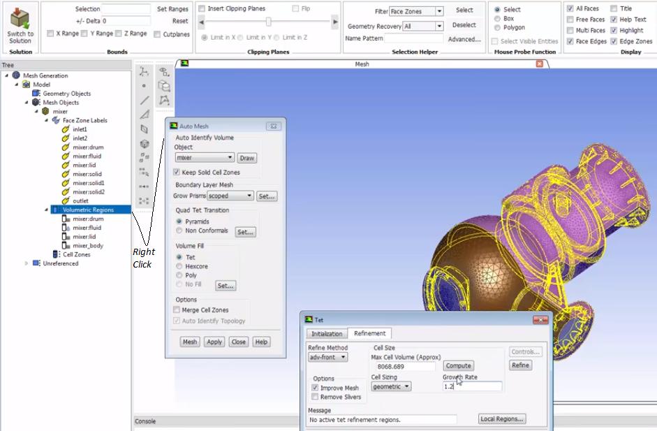
Clean-up operations are performed after the volume mesh has been generated. Operations such as deletion of dead zones and geometry/wrap objects, deletion of edge zones, removal of face/cell zone name prefixes and/or suffixes, deletion of unused faces and nodes are performed. mesh zone-names-clean-up yes. Hexa-core Meshing require two additional parameters: Buffer Layer and Peel Layer. P.L. = 0 implies hexa-core mesh will contain maximum number of Cartesian cells possible for set parameters. P.L. = 2 implies two tetrahedral layers before transition to the Cartesian mesh starts. Buffer layers specify the number of additional layers of hex cells to subdivide before growing to the next level. By default set to 1 but we recommend using 2 or 3 for a slower growth rate.
From TUI Guide: mesh/zone-names-clean-up - Cleans up face and cell zone names by removing excessive characters so that the zone names are easier to read. During the course of creating a mesh, various mesh manipulations can cause the face and cell zone names to become cluttered (with colons, dashes, and numbers for example). Using this command, zone names are reduced to include only the original zone prefix, a single colon, and the zone's ID appended to the end. Removes the ID suffix from face zone names: (tgapi-util-remove-id-suffix-from-face-zones), Clean up face zone names by removing IDs wherever possible: (tgapi-util-clean-face-zone-names), Remove the zone ID (:id) from zone ID list: (tgapi-util-remove-ids-from-zone-names '(zone_id_list))
Replace the face zone suffix to rename face zones. Specify whether to merge the face zones being renamed (set merge? to #t or #f). If an empty string is specified for the separator (" "), the string specified for 'replace-with' will be appended to the face zone names: tgapi-util-replace-face-zone-suffix '(face_zone_list) "separator" "replace-with" merge?). To replace the cell zone suffix: (tgapi-util-replace-cell-zone-suffix '(cell_zone_list) "old-suffix" "new-suffix" merge?). The previous TUI commands shall require following TUI: Return a list of regions in the specified object named obj_name: (get-regions-of-object 'obj_name), (tgapi-util-get-region-name-list-of-object 'obj_name), (tgapi-util-get-region-name-list-of-object "obj_name").(tgapi-util-convert-zone-ids-to-name-strings (get-cell-zones-of-filter '*:*')) produces the list of cell zones containing ':' in their names.
Prism or Boundary Layers
Before proceeding to set parameters for prism (wedge) layers, change volume type to fluid or solid as applicable, check boundary type using TUI boundary/manage/list. This will print boundary name and type. Change inlets and outlets to appropriate type (default is 'wall') else prism shall get generated over inlet and outlet faces as well. Prism Controls have two options:
- Scoped: Fast setup based on volumetric regions having ability to use strings and wildcard character * to scope regions or zones. It can write / read settings and applies by default on all fluid wall boundaries. Proximity is handled with post stair-stepping. Shrinks prisms in areas of proximity to avoid intersections until Gap Factor and Max Aspect Ratio are reached.
- Zone Specific: Setup based on Face Zones only with different proximity handling and improve options (post ignore).
- Uniform: all cells in each layer have the same height. Gives good y+ control and consistent total prism height but may lead to problems with high or low aspect ratio (AR) cells (both can be limited by GUI/TUI parameters).
- Aspect ratio: all cells in each layer have the same AR, robust and useful for large variations in the mesh size on the boundary zone without worry of high/low AR cell creation. No y+ control and inconsistent overall prism height.
- The aspect ratio is defined as the ratio of the prism base length to the prism layer height
- The various growth methods (constant, linear, geometric, and exponential) can be used to specify the aspect ratio of the first layer.
- Last ratio: AR of last layer and the height of the first (wall) layer is specified. Gives good y+ control and ensures good cell to cell volume change at the prism cap. However, inconsistent overall prism height and enough number of layers needs to be specified to ensure good growth.
With options 'Uniform' and 'Aspect Ratio', a sharp change in mesh size (volume) of last layer of prism and first layer of tetra cells can be observed. The option 'Last ratio' can be adjusted to reduce the sudden change in element volumes from prism to tetra.
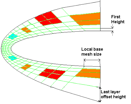
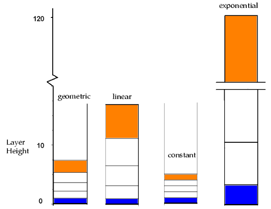
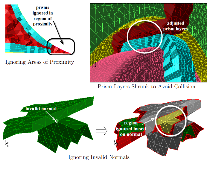
Volumetric (watertight) Regions must be computed before volume meshing. 'Update' recomputes regions but retains any changes to types or names. 'Validate' is a check to verify the regions are closed if modifications have occurred such as zone separation. This will automatically happen at volume mesh stage anyway.
In Automesh panel, 'Compute' Max Cell Volume will calculate based on max edge length in the mesh using perfect tetrahedron formula: volume = √2 /12 × a2 where 'a' is the side length.
If boundary zones are renamed, merged... after volume mesh has been created, deleting the volume mesh prompts to "Restore Boundary Zones". Press 'No' else all the boundary zones shall be changed to type/status before volume mesh was generated. Right click on "Volumetric Regions" and then use the "Info" option: this will print material point name, type, volume, face-zones.... Hex-core Cartesian: "Max Cell Length" is used to generate initial Cartesian cells, Hex-core OCTREE: Hex-core mesh size is used to define mesh size.
| mesh tet improve collapse-slivers | Collapses the nodes of a skewed sliver cell on any one of its neighbors. |
| mesh tet improve refine-boundary-slivers | Increases the volume* of boundary slivers to create a valid tetrahedral cell. |
| mesh tet improve refine-slivers | Removes** the sliver by placing a node at or near the centroid of the sliver cell. |
| mesh tet improve sliver-boundary-swap | Removes boundary slivers by moving the boundary to exclude the cells from the zone. |
| mesh tet improve smooth-boundary-sliver | Smooths*** nodes on sliver cells having all four nodes on the boundary until the skewness value is less than the specified value. |
| mesh tet improve smooth-interior-sliver | Smooths non-boundary nodes on sliver cells having skewness > specified threshold value. Default value = 0.985. |
** Swapping and smoothing are then performed to improve the skewness. You can also specify whether boundary cells are to be refined. Refining the boundary cells may allow you to carry out further improvement options such as smoothing, swapping, and collapsing slivers.
*** Default values for the skewness threshold = 0.985, minimum dihedral angle between boundary faces = 10° and feature angle = 30°- Auto Node Move: reduce dihedral angle from default 120° in steps. This will result in better quality but may result in loss of features. The dihedral angle is the angle between two 'intersecting' planes.
- Feature angle is the angle between adjacent edges. Feature Angle = 20°, if the difference between the normal directions of two adjacent faces is more than 20°, the edge between those faces will be drawn. Decreasing the Feature Angle results in more edge lines (i.e. more detail) being added to the outline display. The appropriate angle for a geometry depends on its curvature and complexity.
Adjust feature angle gradually where 0° implies all nodes are protected and 180° refers that no nodes are protected.
- As a last resort, uncheck "Restrict Boundary Node Along Surface" - though it may cause geometry to get distorted.
Volume Mesh Quality Enhancement
TUI command can be used recursively for auto-node movement: Here 120, 150 ... are the dihedral angles, 50 is the number of iterations. Please note that the values 0.99, 0.98, 0.97... are skewness. Hence, the default quality reporting methods MUST be skewness. In some versions of FLUENT Mesher, default quality parameter is Orthogonality and hence this operation may fail. Use TUI "report quality-method skewness angle" before running the following scripts.
| mesh modify auto-node-move (*) (*) 0.99 50 120 yes 10 |
| mesh modify auto-node-move (*) (*) 0.99 50 150 yes 10 |
| mesh modify auto-node-move (*) (*) 0.98 50 120 yes 10 |
| mesh modify auto-node-move (*) (*) 0.98 50 150 yes 10 |
| mesh modify auto-node-move (*) (*) 0.97 50 120 yes 10 |
| mesh tet improve smooth-interior-sliver (*) () 0.975 50 0.05 where 0.05 is the relaxation factor. |
Mesh ❯ Tools ❯ Tet Improve: remove highly skewed cells with "two boundary faces"
Smoothing of Volume Mesh
Skewness based smoothing: Mesh Tools Tet Improve General - options are Smooth Nodes, Improve and Swap Faces. The 'Improve' method requires "Minimum Improvement Required" which is value which is use to stop the smoothing iterations when change is cell skewness is achieved. There is an internal check to prevent a node from being moved if the node movement causes skewness to increase.
Other smoothing operations in FM are Laplacian Smoothing and Variational Smoothing for Tetras. Laplacian smoothing tend to pull the node away from boundaries and reduce clustering of nodes. Variations smoothing is complement to Laplacian smoothing where new node position is weighted-average of circumcentre of the cells connected to the node.
Bad quality and sliver cells can be displayed and manually split (each cell shall be split into 4 by placing a node at the centroid) / merged to improve the quality using the feature Mesh Tools Cell Modify Quality. However, before using these operations, display the poor quality cells using Display Grid Cells Quality. Tick the 'All' checkbox under Nodes, Edges and Faces tabs.
Once mesh quality improvement operations are complete, untick the 'Quality' options under Mesh Tools Cell Modify Quality. The TUI path to collapse slivers in volume mesh is mesh tet improve collapse-slivers (*) () 0.985TUI: report verbosity-level specifies how much information should be displayed during mesh initialization and refinement and other operations. Changing the value to 2 from the default value of 1 will result in more messages while changing it to 0 will disable all messages.
A sample checklist for mesh can be as short as shown below.
- Has the cell zone and boundary zones named as per 'some' naming convention?
- Has all the boundaries with no default attributes named with a identifier b_def_id?
- Has the skewness for surface mesh been reduced to ≤ 0.70 and that for volume mesh ≤ 0.85?
- Has the aspect ratio of volume mesh been reduced to ≤ 50 in boundary layer prisms and ≤ 10 in freestream tetrahedrons and hexahedrons?
Prism Layer Splitting
After prism layers are generated, prism layer splitting also supported with options to change growth rate based on total height.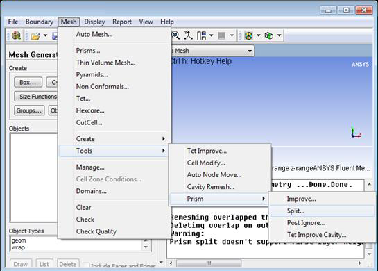
View Volume Elements on Iso-planes or Section planes
Switch to node filter -> Select a node at the desired location of iso-plane -> Set +/- Delta as zero and click Set Ranges -> Deselect X Range and Y Range, leaving only Z Range if cut plane is aligned to XY-plane. From main menu: Display -> Grid panel -> In the Cells tab, select the desired Cell Zone -> under Options, tick Bounded then click Display to show volume (3D) elements on the iso-plane. Alternatively, select the zone under Mesh Objects in model-tree and click RMB on Cell Zones -> Draw All Cells in Range.
Common issues with mesh
Warning: 3 cell(s) have only wall faces... this means volume mesh is topologically not correct. The mesh needs to be separated using TUI in FM:mesh separate separate-cell-by-region fluid
where 'fluid' is the name of the volume mesh.In FLUENT Pre-Post, the TUI option is: mesh modify-zones sep-cell-zone-region. The TUI mesh mesh-info 0 (here 0 is the grid level^) or GUI path Mesh Info Zones can be used to find out the new redundant cell zone (it will have few cells only, 3 in this example). Thereafter, the inconsistent zone can be deleted.
^ - For density-based coupled explicit solver, the mesh information is printed for each grid level. The grid levels result from creating coarse grid levels for the Full-Approximation Storage (FAS) multigrid convergence acceleration.
Some tips and tricks of mesh generation:
- Delaunay method of mesh generation typically results in smoother transition from coarse mesh to fine mesh regions. Most of the meshing programs have provision to use an existing surface mesh to generate the volume mesh.
- Sometimes, ICEM CFD is not able to generate surface mesh if the surface has strong curvature or iso-lines are not well defined. The surface mesh can be generated by
- creating volume mesh using more robust OCTREE method
- deleting volume mesh
- repairing surface mesh
- smoothing surface mesh with Laplacian smoothing switched OFF
- smoothing surface mesh with Laplacian smoothing switched ON and finally
- smoothing surface mesh with Laplacian smoothing switched OFF.
- Once a good quality surface mesh is available, Delaunay method can be used to generate good quality volume mesh with better transition from coarse mesh region to fine mesh region and vice versa.
Mesh Exchange across Applications
If mesh generated in FM has unit of [mm] and it is scaled to [m] in ANSA, when the mesh is re-exported to NASTRAN format, it will maintain the length unit [mm]. When the NASTRAN mesh is imported into COMSOL, it will use [mm] as length unit and hence the length unit need to be changed appropriately. Since most of the solvers work on SI unit internally irrespective of the units used to set-up the case, it is better to scale the mesh in source (e.g. FLUENT Mesher: Mesh ❱ Manage ❱ Scale. Do not use Boundary ❱ Manage ❱ Scale operation).Mesh to Geometry
Sometimes, meshed surfaces need to be converted into geometrical entities say to generate a better mesh, change the domain size or use a different program for simulation. One common method is to use STL format for this purpose though it shall result in highly skewed cells if the original mesh comprises of thin boundary layer (quad) cells. Few options which can be tried out to make the input mesh more uniform are [1] Wrapping, [2] Merging or remeshing surface elements having area < a threshold value. However, be aware of the edges with included angles > 150° where the remeshing approach may lead to violation of sharp boundaries. Edge zones becomes extremely important dealing with faced geometry. In ANSYS FLUENT Mesher, edge zones can be separated (split) following Boundary > Mesh > Feature > Edge Modify > Separate. Angle can be specified for separation (edge split) criterion.
Some other operations required before re meshing are: (a) Rezone a Face: move faces to a new zone especially where sharp edges exist (b) Split highly curved surfaces appropriately into small segments so that they can be approximated with regular surfaces (c) Global retriangulation: re-triangulate all the surfaces to get rid of sliver elements. (d) Create Edge Loops: in FLUENT Mesher, Edge Loops can be created according to either (i) the edge loop creation approach (having further two approaches: "Face Zone Approach" and "Face Seed Approach") or (ii) the angle criterion (having options based on "Fixed Angle Criterion" and "Adaptive Angle Criterion".
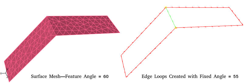
The interior edge thread at the common edge is created when the specified value for "Fixed Angle" is < the feature angle. In other words, a common edge is considered to be a feature edge when the angle value specified (fixed angle criterion) is less than the feature angle.
ANSYS Discovery (previously known as SpaceClaim) has a feature Auto Skin that generates CAD geometry from faceted boundaries that are relatively smooth and error free (no sharp edges or self intersections). If the model boundary is not smooth, the CAD geometry creation may fail or result in incorrect geometry such as CAD geometry may not be confined to the boundary of the faceted area. It also has Skin Surface tool to sketch and create surface patches on the facets, and stitch them together into a surface body. Single-click the mesh starts the sketch and adds internal edge points (can be moved to adjust the shape of the edge), double-click ends the edge selection and creates a corner. To create rectangular patches, use box-select instead of sketching by freehand mthod. There is another feature Extract Curves to create geometry edges on section planes. Fit Spline tool creates a "best fit" spline surface through selected mesh facets.
Mesh Transfer using FE Modeller: As per article titled "How do you transfer a mesh from ICEM CFD into Workbench Simulation?" posted on innovationspace.ansys.com - Write an unstructured mesh from ICEM CFD → Insert an FE Modeler component → When "add[ing] input mesh" select the extension as "ICEM Input (*.uns)." → Open FE Modeler and right click on "Geometry Synthesis > Insert > Initial geometry." → Left click and drag the 'Model' cell of the FE Modeler system to the 'Model' cell of the Simulation analysis system.
Mesh Exchange between Various Programs
Most pre-processors have option to save the mesh information in binary and ASCII formats. Pre-processors like ANSA can read the FLUENT mesh (both surface and volume meshes in *.msh and *.cas formats) directly. However, the mesh information (the file) needs to be saved in ASCII format.Mesh Generation in ANSA
ANSA can read OpenFOAM, FLUENT, STL and many other mesh with zone (PID) names defined in the input mesh. Starting ANSA for CFD Application: 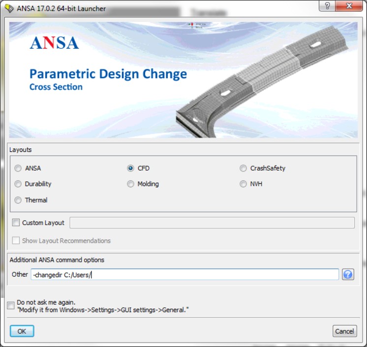
- The left mouse button is mainly used to: activate modules buttons, select or define entities. The double click of the left mouse button is mainly used to: edit entries in lists, control visibility by clicking on the screen
- The middle mouse button is mainly used to: declare the end of a selection process, cancel the currently activated function
- The right mouse button, depending on the function, is mainly used to: deselect previously selected items, reapply last action to other entities, pick closest point position (Working Plane mode), access the right click menu in lists, activate hidden windows, select buttons to custom place them on ANSA desktop panel. The double click of the right mouse button is mainly used to: control visibility by clicking on the screen
- The mouse-buttons combined with the Control (Ctrl) key, are used for the View control. Mouse-buttons combined with the Shift key, are used for the definition of a polygon selection area.
- F7: zoom-in, F8: Zoom-out, F9: fit to window
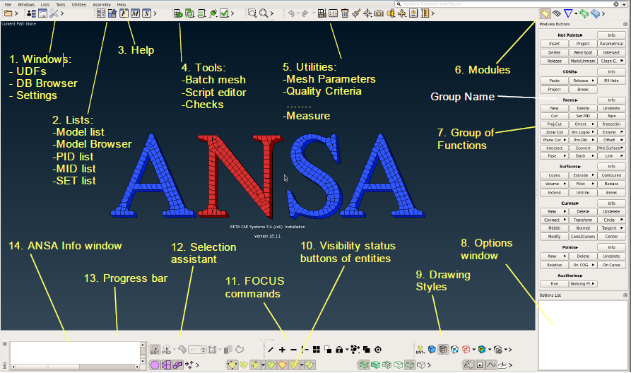
- TOPO - for geometry creation, manipulation, clean-up and watertight preparation
- MESH - for surface and volume mesh and fix
- DECK - for solver related features and the creation of Size Boxes for controlling mesh size
- MORPH - for mesh and geometry morphing
- HEXABLOCK - for hexa meshing based on block structure of boxes
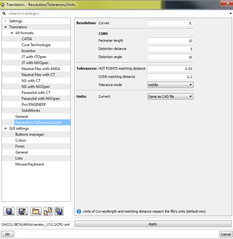
ANSA Geometry Import Setting:
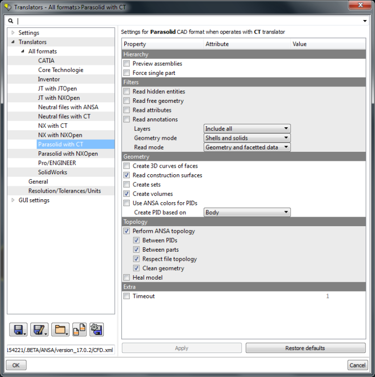
The concept of Feature Area, which is defined according to the feature angle, is widely used in many functions in ANSA. The Feature Area is defined as the area of shell elements between whom the angle that is formed at their common edge is < the given feature angle. This is equivalent to "fill up to an angle" in ICEM CFD. Similarly for edges "Feature Line" selection tool uses the concept of "Corner Angle" which is defined as the angle formed by two consecutive element edges.
ANSA Geometry Check Options: 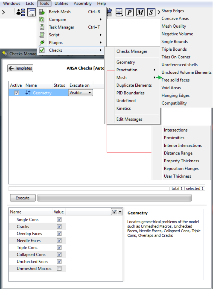
SETs: for management of SET groups of ANSA entities like elements, properties, Faces, ... The CONS (Curves ON Surfaces) are the boundaries of the Faces. According to their connectivity, they are colored in Red (single edge), Yellow (double connectivity), Cyan (triple of more connectivity), orange when a double CONS has been joined. The Hot Points are the end points of CONS. A more handy way to deal with Faces is to use the Crosshatches. These appear as green dashed lines and represent the isoparametrics of the Surface on which the Face lays. A Face can be selected by its Crosshatch. In case that a Face is “frozen” (by the Freeze function), its cross-hatch is colored in blue.
Use the function CHECK > GEOMETRY to identify and fix automatically some problems. Watertight preparation: Having extracted the outer surfaces, you must create the watertight model by sealing all gaps and eliminating the overlaps. If these gaps are small (close to the Tolerances), they can be closed by TOPO or PASTE functions. If they exceed (by far) the tolerances, then new Faces must be created (usually with SURFs>COONS) to close them.
Checking for intersections and proximities at Geometry level: You should make some checks for intersection and proximity while constructing your model. First of all, use the CHECKs > PENETRATION [Intersections] to locate intersecting areas (wrong topology, misplaced parts etc). Fix these areas using TOPO functions (like FACEs>INTERSECT). Use the ISOLATE > FLANGES [Proximity] function to isolate Faces within a certain distance apart. This will indicate you all the proximity problem areas that may cause problems in volume meshing. Then use the FACEs>FUSE function to close these narrow proximity passages, where possible.
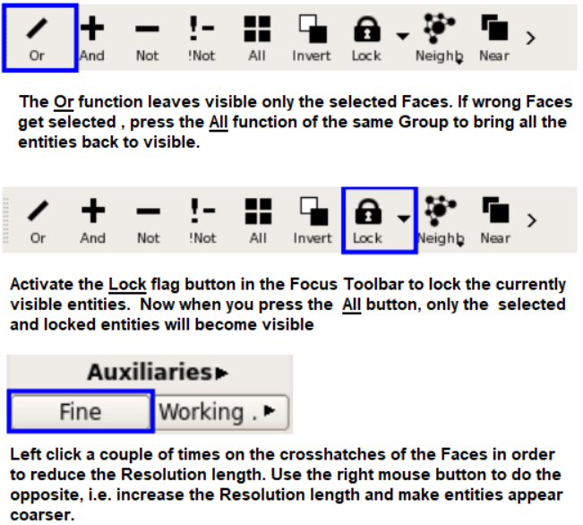
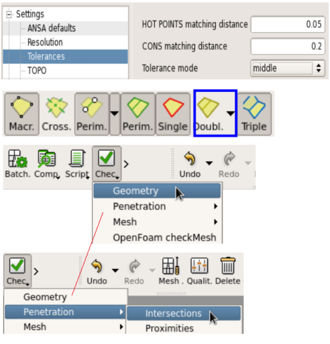
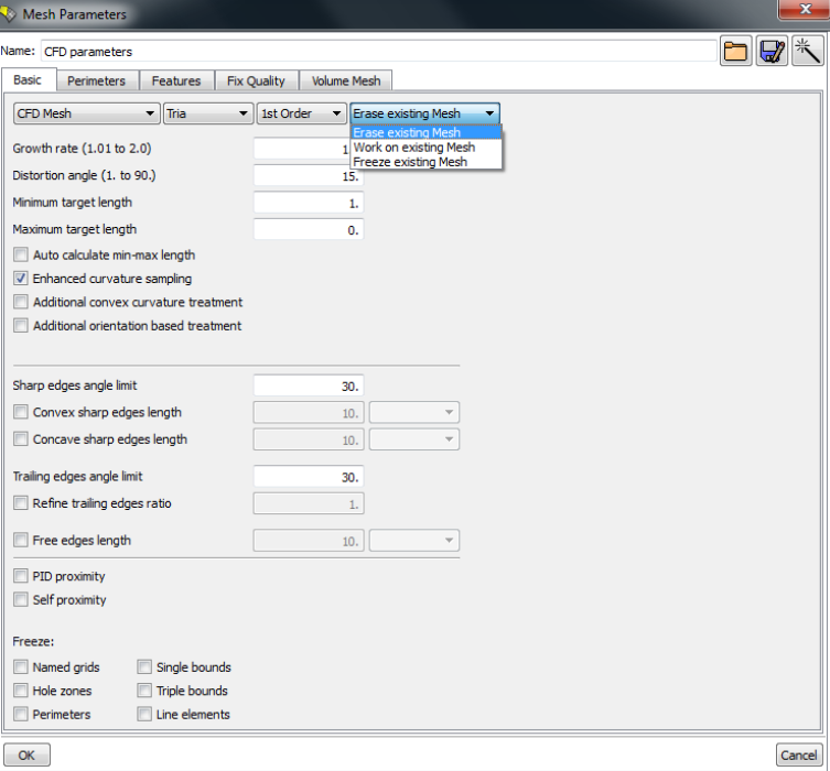
Before switching to MESH, activate SHADOW and FOCUS>UNCHECKED. If ANSA leaves any Faces visible, it means that they cannot be shaded and you should fix them also.
ANSA Volume Meshing Parameters Setting: 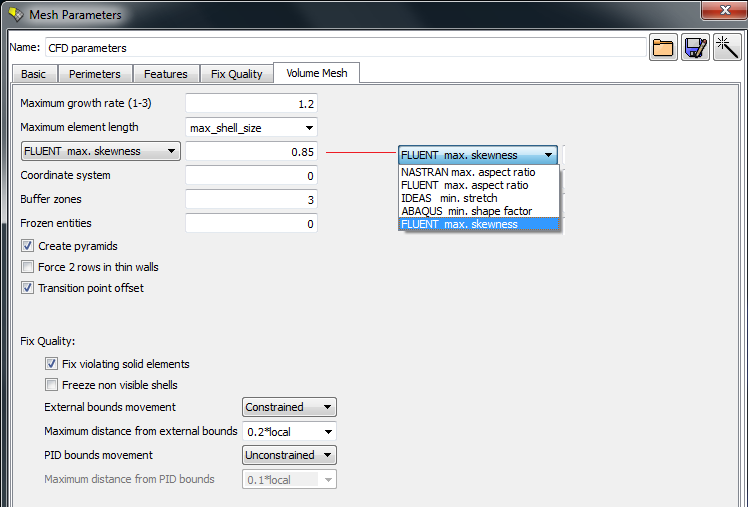
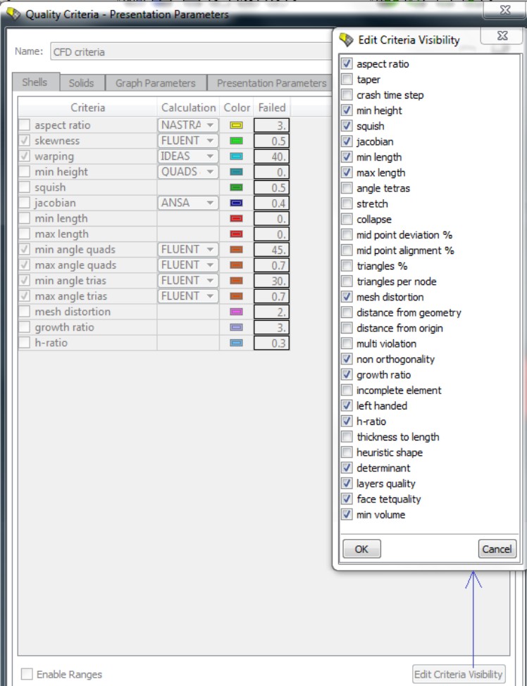
Leak Detection in ANSA
In addition to perform a visual inspection of the model in Display Styles > TOPO Check Gaps and Display Styles > MESH Check Gaps to see if there are red single bounds in the model, there are 3 ways to identify leaks on complex mesh models with gaps, overlaps and intersections.Method-1: Isolate > Skin function
Step-1:Selects whether to isolate exterior or interior geometry.↓
Step-2: Specify excluded volumes, that is positions in space where ANSA should not find a path from the exterior.↓
Step-3: Select from the screen point position to extract their CoG and confirm. More than one seed points can be specified. 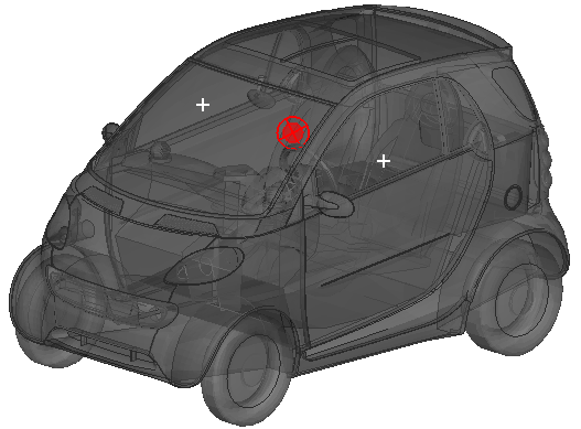
↓
Step-4: Based on the user specified value of leak size if ANSA finds a path from the exterior to the seed points then it will create a 3D curve indicating the leak patch through the opening.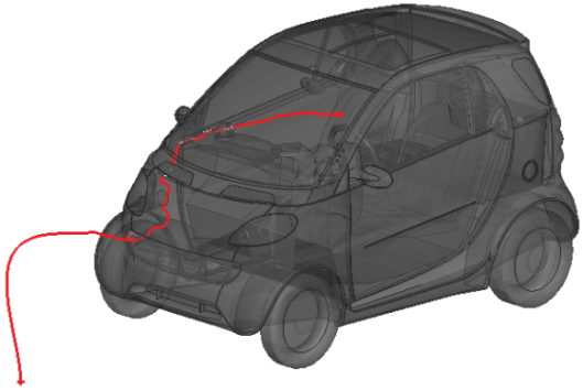
Method-2: Elements > Wrap [Variable length] function
The function provides an integrated leak check tool with an additional advantage with respect to the previous method, the fact that it uses a variable length Octree that adapts to the local length.ANSA wrap algorithm will run and if there is a leak will stop and create several 3D Curves. This allows the user to trace and locate multiple leak areas in one step.
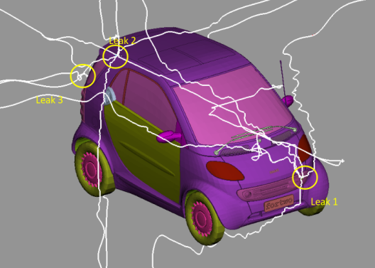
Method-3: Elements > Short Path [Leaks] function
This method can only be used on good quality mesh (not STL mesh with intersections and other problems) if there is a suspicion that there is a leak which is not easy to locate in a complex model, and the automatic Volume detection algorithm fails.Step-1: Specify one outer point (green) and one (or more) inner ones (red).
↓
Step-2: Points must NOT lie on the surface mesh but inside or outside the volumes in question. To select easily a point that lies inside the volume and not on the surface, select more than one points and ANSA displays the CoG of them and highlights it.↓
Step-3: Then proceed with the next source point, select many nodes on the surface, ANSA displays the CoG. Finally confirm all selections with middle mouse and ANSA will calculate a curve of the Leak Path, if such a path exists.
↓
Step-4: The leak can be found by tracing this path.
ANSA: Model Generation Checklist
ANSA user manual has a very effective checklist to guide users to get a high quality mesh.| Geometry Preparation | |
| Faces Resolution | Different models require different discretization length. Assign a suitable element length on your model from Mesh > Perimeters > Length or Spacing [Auto CFD]. This will allow you to better display the model details. |
| Faces Orientation | Activate Visibility > Shadow mode. All Faces should be uniformly oriented. Gray is the positive side and yellow the negative. Use Faces > Orient to assign uniform or invert the orientation. |
| Unnecessary Hot Points | Perform a Hot Points > Delete with box selection to remove any unnecessary Hot Points. |
| Check> > Check Manager > Geometry Checks | The user can use the Checks>Checks Manager functionality to identify several common problems in one click.Use the template Geometry Checks to find all the problems. ANSA will report all the problems. Double clicking on each category will allow the user to right click and isolate or automatically fix the problems (if possible). Triple CONS may exist in a CFD model on purpose. Single CONS should only exist if the model has zero-thickness walls (baffles). If any penetrations are identified, the user should use the function Faces>Intersect to fix any intersecting parts. |
| Isolate > Flanges > Proximity | This check will identify parts that are very close together (although not actually intersecting). The absolute distance value is left to the user to decide. Very often such geometries also need to be topologically connected, using Topo functions like CONS>Project and Faces>Topo. |
| Surface meshing | |
| Perimeters > Length or Perimeters > Spacing [Auto CFD] | Ensure that you assign to all Perimeters the desired Element Length. For uniform element length mesh, use Perimeters > Length, while for variable, curvature dependent surface mesh use Perimeters > Spacing [Auto CFD]. |
| Unmeshed Macros | After using the various meshing algorithms (Adv. Front, CFD...) the user should check for Unmeshed Macros in the legend on the left. Use right click for Show Only and then use alternative algorithms or cut them into smaller macros, or check the underlying geometry. |
| Visibility > Hidden OFF elements | Switching to Hidden mode allows you to check if there are violating elements, reported in the legend as OFF. Use Shell Mesh > Reshape [Advanced] to fix them automatically (perform twice if needed). If there are any remaining OFF elements, then use right click Show Only on the legend OFF to identify and examine these areas. You may have to use Shell Mesh > Fix Quality or even change the geometry or the element length to better resolve such areas. Do not proceed to layers or volume meshing if you still have OFF elements on the surface. |
| Surface mesh orientation | If layers are to be generated ensure that the orientation is uniform and correct for the whole of the model. Use Macros > Orient. |
| Checks > Checks Manager > Surface Mesh Checks | Use the Surface Mesh Checks template of the Checks Manager to identify all the problems of the surface mesh. Unmeshed Macros and Intersections Sharp edges: This check will identify very sharp angles in the surface mesh. These may be due to flipped elements on the surface or to the actual nature of the geometry. Such areas may cause problems, especially for layers generation, so you should treat them
appropriately.
Trias on Corner: identifies triangles at three edge corners and swaps them if needed so that layers with better quality can be generated afterwards. Duplicate and Triple Bounds: will identify duplicate elements or triple connectivity edges. Check for proximities that may lead to problems in layers of volume meshing. The check distance can be an absolute value, but it is better to specify an element length factor (< 1). This implies that the check distance will be equal to the factor multiplied by the local element length. Activate also the options to check proximities among areas with the same PID (self-proximity) and provided that you have oriented your shell mesh (Macros > Orient) correctly, check only the positive side (gray one) for proximities. |
| Volume meshing | |
| Volumes > List | After layers generation, ensure you have the whole model visible and use the function Volumes>Define [Auto Detect] to automatically identify all volumes. Mesh them with Volumes > Mesh Volume. Open the Volumes > List and check that all volumes are marked as Meshed. Check also that they have correct Property Name (Use Volumes > Set PID if needed). Select a Volume and press Info to get quality information. |
| Visibility > Hidden | Switching to Hidden mode allows you to check if there are violating elements, reported in the legend as OFF. You can optionally press right click Show Only on the OFF legend to isolate them. To fix them, press Focus > ALL, ensure that the visibility of Macros, FE-mod and Volumes are all active and then use Volumes > Improve > FixQual [Visible]. You may have to press the function again in order to fix any remaining elements. |
STAR-CCM+ Mesh Import Options:
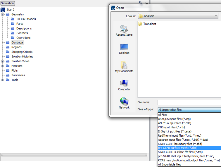
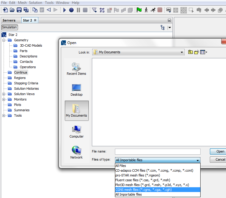
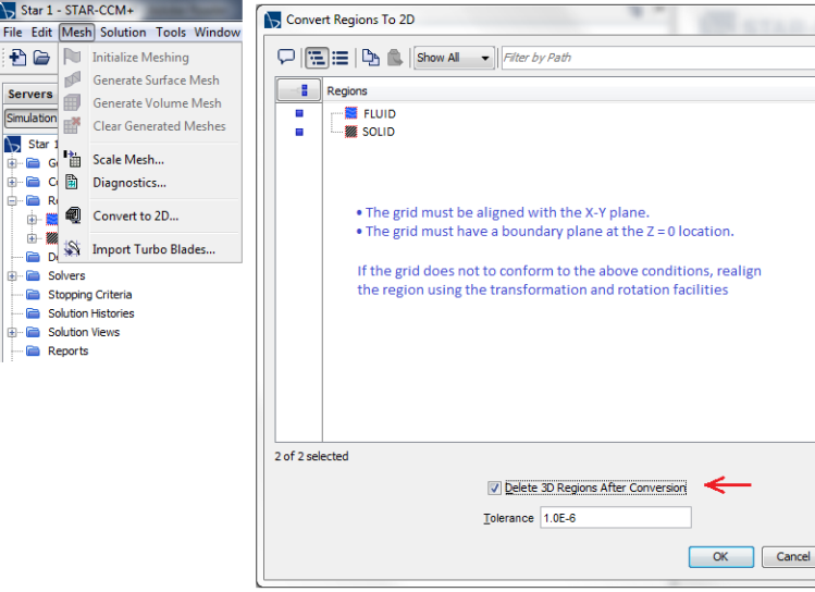
COMSOL Meshing
COMSOL is a Finite Element Method (FEM) based solver in contrast to other programs which are Finite Volume Method (FVM) solver.
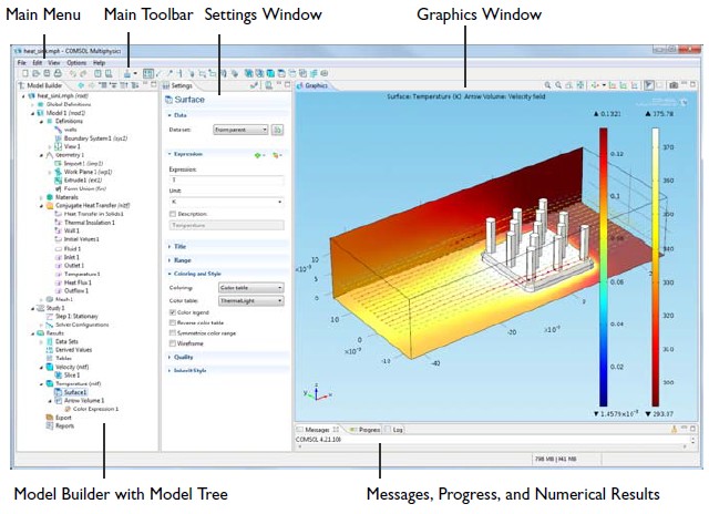
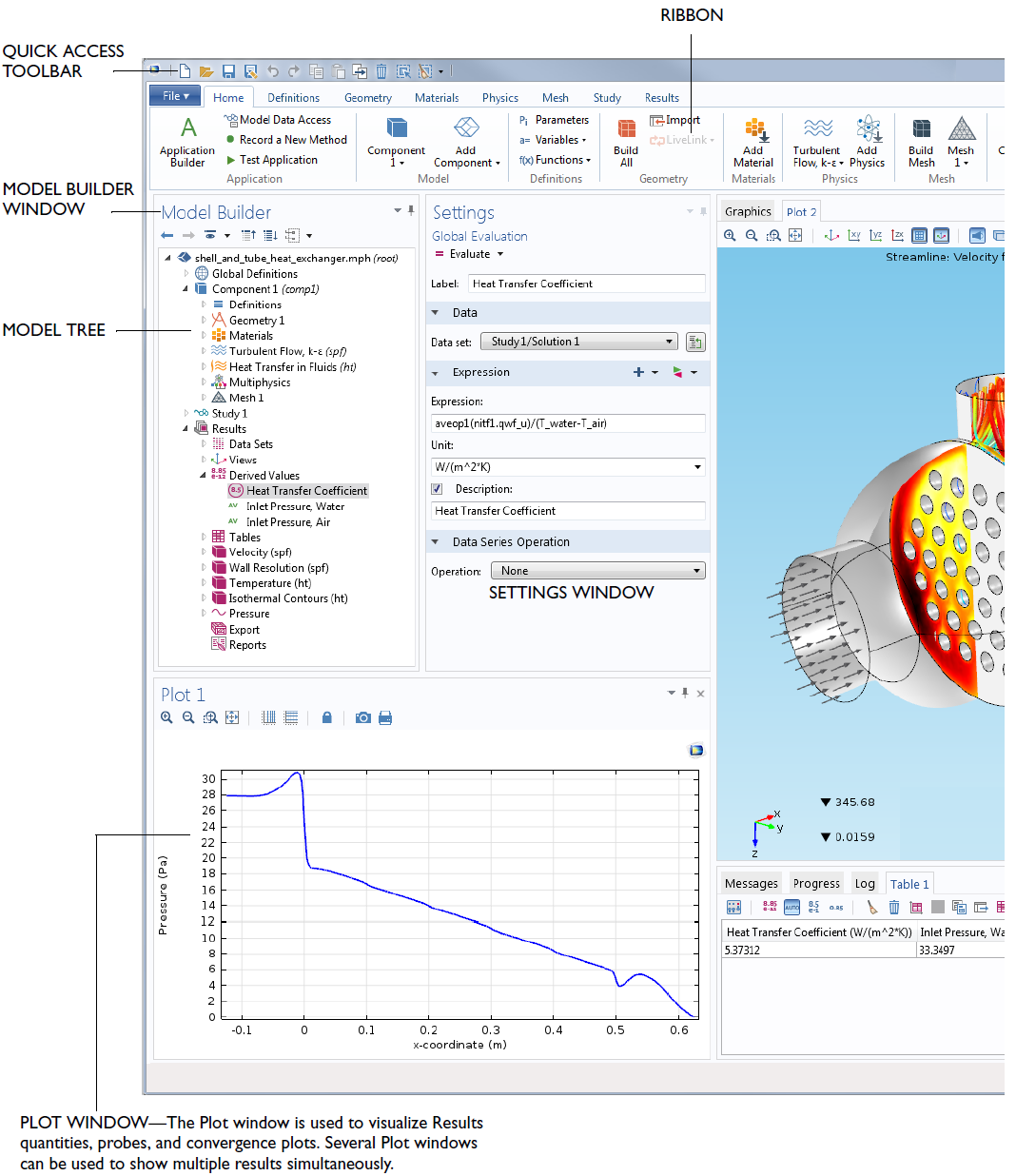
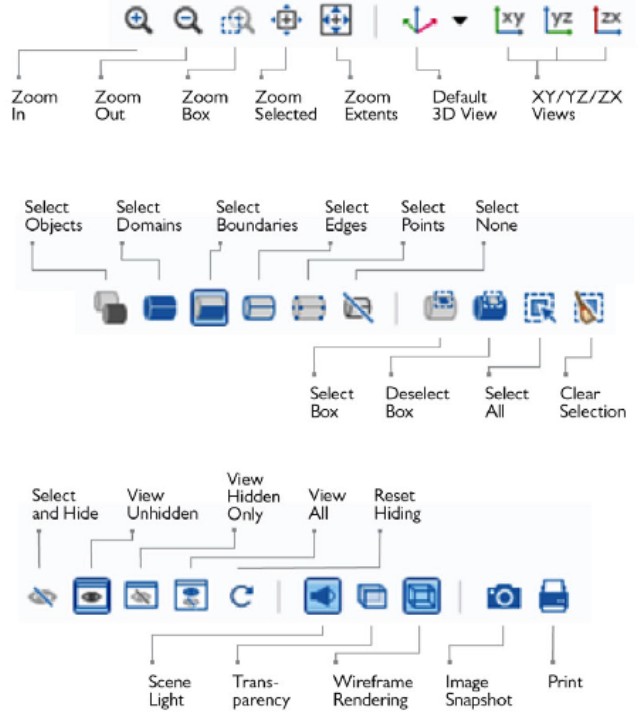
Some operations and key-board short-cuts:
- Clicking middle mouse button in the graphics window sets the rotation (spin) centre
- Separation of elements in zones is called 'Partitioning'. Elements can be selected within a sphere or cylinder... very similar to patching operation in FLUENT solver (used for local initialization).
- The STL mesh imported into COMSOL can be made more uniform, refined or coarse by Adapt operation. Select 'Solution' variable as 'None'. Start with very fine mesh size and then perform multiple adaptation to get desired mesh.
- 'Filters' are used to select elements or make plots as per defined criteria. For example, under "Element filter" the logical expression "x > 0" shall plot elements with positive x-coordinates only.
- "Create Domains" under Mesh part ↠ Create Entities is analogous to "Compute Volume" in FLUENT Mesher. This creates initial volume of the cell zones.
- Create Faces and Fill Holes are similar to Create Patches in FLUENT Mesher.
By default, COMSOL maintains SI system of unit for solved variables. To plot temperature in [°C] unit, create a new express Tc = T - 273.14 using operation Definitions ❱ Variable. Similarly to specify simulation input such as reference temperature, use expression Tref = 25 [degC].
In order to import STL into COMSOL, make sure that it is well-defined: no intersections, no holes, all triangles attached to each other (overlap). COMSOL applies a "Boundary partitioning" algorithm when importing STL meshes. This algorithm fits smooth, curved surfaces through the STL triangles, reducing the number of boundaries in the geometry. Using a Minimal boundary partitioning creates as few faces as possible — sometimes only one. The Minimal setting is usually a good choice when the source is a 3D scan. The default Automatic boundary partitioning is best suited for cases where the imported mesh has a natural face partitioning (i.e. when the mesh is from a CAD file). There is also an option to manually set the parameters by choosing Detect faces.
- For times when changing the Maximum boundary neighbour angle is not satisfactory for one's needs, adjust the Minimum relative area and the Maximum neighbour angle.
- The Minimum relative area setting limits how small the detected planar faces can be relative to the total area of the surface mesh
- The Maximum neighbour angle setting sets the maximum tolerated angle between neighbouring boundary elements in the same planar face.
It is better to omit this step. In the Import node, select "Detect faces" for the option "Boundary partitioning". Then, set "Maximum boundary neighbour angle" to 0 and disable "Detect planar faces". COMSOL mesher is then bounded to preserve the triangle edges, which could results in a mesh that is finer than necessary and possibly in worse element qualities. Therefore, STL mesh can be generated as coarse as deemed appropriate before importing it into COMSOL.
Selection of Entities in COMSOL
- Hover and click: general selection of visible and easily accessible boundaries
- Hover and scroll button: for selection of interior geometries
- Graphics selection: box selection of entities completely encompassed by the box
- Selection List: Select entities by ID - Windows ❱ Selection List
- Copy and Paste selection
- Pre-selection: to apply physics and boundary conditions through Ribbon Tab
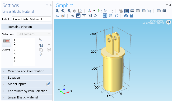

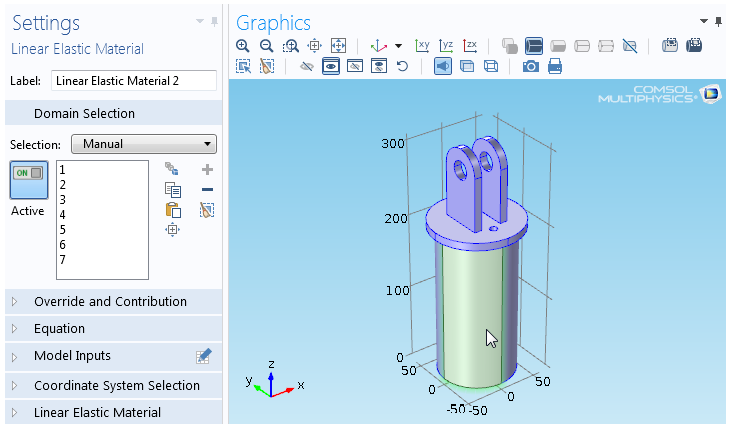
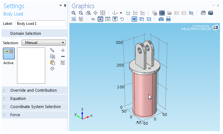
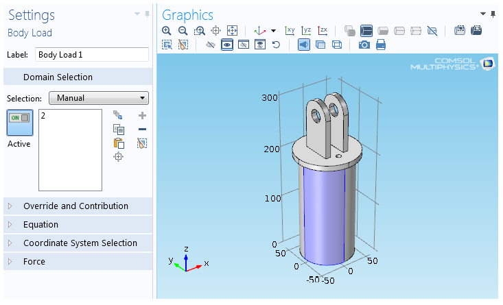
Import Meshes into COMSOL
It is only possible to import a mesh if the geometry sequence is empty. If the sequence already contains a mesh, the imported mesh is added to the existing mesh, forming an assembly.
When a mesh is imported into COMSOL, the Import node automatically determines a partitioning of the mesh into domains, boundaries, edges, and points. If the automatically performed partitioning does not match the requirements, you can modify the face partitioning by manually adjusting the corresponding parameters.To import additional meshes, add another Import node. Then COMSOL adds the elements and points of the newly imported mesh to the existing mesh. Meshes from different Import nodes form an assembly. The Finalize node ends a meshing sequence of imported type. It performs an associativity update for geometric entity numbers. You cannot delete, disable, or move the Finalize node. The software automatically builds all nodes in a meshing sequence, including the Finalize node, if you select a node in Model Builder outside the meshing sequence.
Using Several Meshing Sequences of Imported Mesh Type
You can define several meshing sequences for the same geometry. If the geometry sequence is empty (a necessary condition for the Imported mesh sequence type), the first Mesh node under the Meshes node defines a topology and is referred to as the master sequence. All the other Mesh nodes should define a geometry topologically similar to the one defined by the master sequence. Two geometries are considered to be similar if they have the same number of geometric entities and their points have the same coordinates. Imported mesh can be remeshed to create a new mesh more suited to solving the problem at hand.It is possible to import externally generated mesh data using a COMSOL mesh file. The file format contains a section with mesh points coordinates, followed by sections with mesh element information, divided into separate subsections for each mesh element type.
Importing a mesh clears the geometry defined in the corresponding geometry sequence. In order to use an imported mesh together with an existing geometry, import it in a separate component. Then use the Copy or geometry Import features to transfer the mesh to the geometry sequence.
STL Import
When a a STL (surface) mesh is to be imported into COMSOL, it should be imported as 'Geometry' object and not as 'Mesh' object or 'part' as it is called in COMSOL. This step automatically creates a 'Mesh' part under 'Model' tree on the left of the GUI workspace. In case mesh part is not created or gets deleted accidentally, use "Add Mesh" option under 'Mesh' menu and apply "Build All".During the mesh import, the geometry can also be created with smooth edges and faces and even creates solid objects from surface meshes with a 'watertight' region. Though the surfaces are interpolated and hence are not exact. Due to this, surfaces of an STL sphere, for example, are not perfectly spherical. It is also difficult to combine these objects when they are expected to contain perfectly matching faces that are supposed to touch..
Note that mesh files do not contain information about the Length unit, so this must be set manually in the settings windows of the Mesh Part and the Geometry nodes.
Once the surface mesh is imported, the water tight domain can be created using "Create Entities" options. When a volume mesh in NASTRAN format is imported, the volume (domain) gets created during import operation itself in case no error is reported by COMSOL. However, one need to adjust length unit of the imported mesh using operation Geometry ❱ Settings ❱ Length Units. Operation Options ❱ Preferences ❱ Modeling ❱ Units sets the unit for user input though the solver still maintains "Base Unit" as SI system internally. Please test out the effect of toggle option "Scale Value when Changing Units" while using operation Geometry ❱ Settings ❱ Length Units.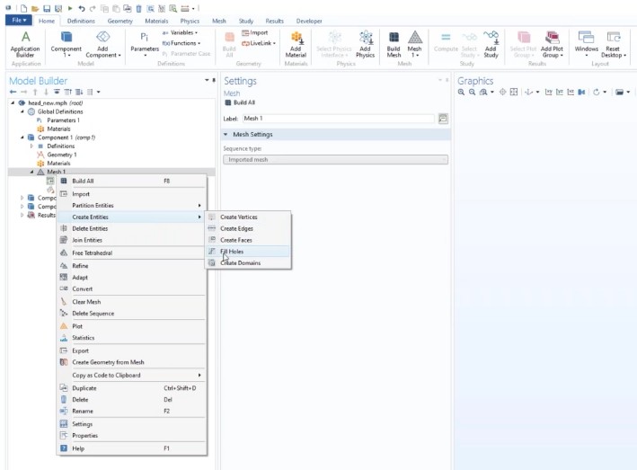
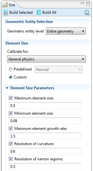
NASTRAN Import
When a NASTRAN bulk data file is imported into COMSOL Multiphysics, the software imports mesh and material information only. To import mesh and material data from a NASTRAN file select Mesh and materials in the Data to import list. In this case, COMSOL creates Material nodes corresponding to the data in any MAT1 and MAT10 entries in the file. Furthermore, the thickness data of any PSHELL entry in the file is stored in a Variables node as long as it is greater than zero. To simplify the use of this data in physics interfaces, such as the Shell interface, an Explicit Selection node, which contains all boundary faces associated with PSHELL entries, also appears automatically. If the material data is not required, select Only mesh to import the mesh only.Mesh information is read from different NASTRAN entries, including those for mesh elements of lower dimension. When this information is not complete in the file, COMSOL enriches the imported mesh data with boundary elements, edge elements, and vertex elements such that a valid mesh object is formed. Each element in the imported mesh object receives a unique entity index.
- To use material data in the file to determine the partitioning of the elements, select the Partition according to material data check box (selected by default). Choose Create selections to automatically generate selections corresponding to the groups of domain and boundary elements in the file. These selections become available for specifying geometric entities throughout the component e.g. in Material nodes and physics interfaces.
- Choose Allow partitioning of shells to allow the boundary partitioning algorithm to split the boundary entities that are defined based on the data in the file into smaller parts. Both options are selected by default.
- To use element types in the file to determine the domain partitioning of the domain elements, select the Partition according to element type check box (not selected by default).
- To import the elements in the NASTRAN file as linear elements (that is, ignoring node points not in element vertices), select the Import as linear elements check box (not selected by default).
Operations on Imported Meshes: The following mesh import operation nodes make it possible to define the partitioning of an imported mesh into domains, boundaries, edges, and points, with respect to the physics interface settings of the Component.
- Ball: To split geometric entities in an imported mesh by an element set defined by a ball. It operates on the boundary level and requires radius and centre of the sphere.
- Box: To split geometric entities in an imported mesh by an element set defined by a box. It operates on the boundary level and requires coordinates of the lower-left and top-right corners.
- Create Vertex: To create an additional vertex in an imported mesh.
- Cylinder: To split geometric entities in an imported mesh by an element set defined by a cylinder and operates on the boundary level. It requires radius of the cylinder, location of top and bottom faces, position on the cylinder axis and axis direction.
- Delete Entities: To delete geometric entities from an imported mesh.
- Detect Faces: To split the geometric boundary entities in an imported mesh by detecting shapes that are likely to constitute faces. To add a Detect Faces node, right-click a 3D Mesh node and select Detect Faces from the Partitions submenu.
- Join Entities: To join adjacent geometric entities in an imported mesh. It operates on the domain level (that is, add All domains to the selection). It results in a mesh for a model with a single domain.
- Logical Expression: To split geometric entities in an imported mesh by specifying a logical expression. It operates on the boundary level: example expression: (y + 10)^2 + (z - 10)^2 <= 16 ) to define a cylinder of radius 4 [units] of extending in X-axis centred at [Y = -10, Z = 10].
- Select Automatic to let the software partition the boundary elements into boundaries automatically (the default setting).
- Select Minimal to make a minimal boundary partitioning. This is useful when you import a mesh from a measured geometry or a NASTRAN mesh with a predefined boundary partitioning. The automatic face partitioning is not desired then.
- Select Manual (in 2D) or Detect faces (in 3D) to manually control the partitioning. Both choices add a set of parameters, which make it possible to influence the result of the partitioning algorithm.
Importing Incomplete Mesh Data: A COMSOL mesh contains elements for all space dimension levels. For example, a tetrahedral mesh consists of domain (tetrahedra), boundary (triangles), edge, and vertex elements. Furthermore, each element has an index to the geometric entity it belongs to. If a mesh file is incomplete - for example, if it only contains tetrahedrons - the Import operation automatically generates the missing element data.
Steps to Prepare Imported Meshes for Analysis
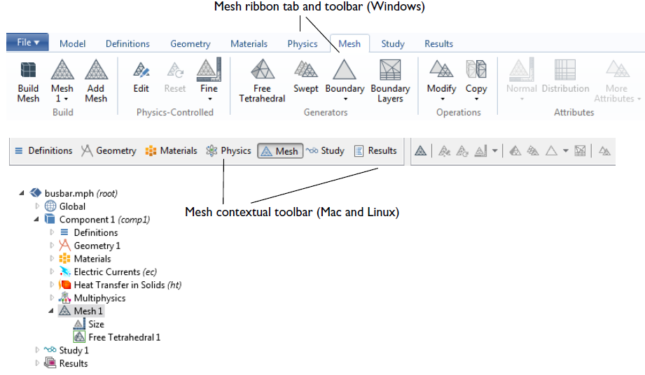
COMSOL can import volume mesh created in other pre-processor in NASTRAN format only. Surface meshes in STL, LPY, VRML and 3MF formats can also be imported. FLUENT Mesher cannot save mesh directly as NASTRAN format. One round-about process is to save FLUENT mesh *.msh as ASCII format ❱ Import the mesh in ANSA ❱ Export the mesh as NASTRAN format ❱ Import the mesh in COMSOL (ignoring the material).
In case surface meshes are imported, follow the steps mentioned below.
- Import mesh with appropriate selection of "Boundary Partitioning".
- Repair or fill holes by Mesh ❱ Create Entities ❱ Fill Holes. This step is analogous to Stitch, Join and Intersect operations in FLUENT Mesher.
- Remesh (refine and/or coarsen) boundary faces/zones if needed: Mesh ❱ Adapt
- "Create Domain" once water-tight geometry (mesh) gets created. This step is analogous to "Compute Volume" in FLUENT Mesher.
- Generate mesh by operation: Mesh ❱ Free Tetrahedron. This step is analogous to "Auto Mesh" in FLUENT Mesher.
- Select the meshing sequence with the imported mesh.
- On the Mesh toolbar click Create Geometry from Mesh or right-click and select it from the context menu.
Reusing The Original Mesh: It is possible to use the original, imported mesh, or parts of it, in the new Component.
- Add a Copy feature to the meshing sequence.
- Select the original import sequence as Source Mesh.
- Select source and destination entities.
- Click the Copy button to copy the mesh. If you have added more geometry, you can use the usual mesh operations to add mesh to these entities. You can also add boundary layers to the copied mesh.
Associative CAD interface
This features refers to the capability to read Parameters defined in CAD programs into FEA pre-processor such as ANSYS Workbench (DesignModeler and SpaceClaim). This can be set using utility ANSYS CAD Configuration Manager and turning ON required Workbench Associative Interface radio buttons - as shown below in image at forum.ansys.com. Note that native CAD reader plug-in or add-on is not same as Associative Interface plug-in.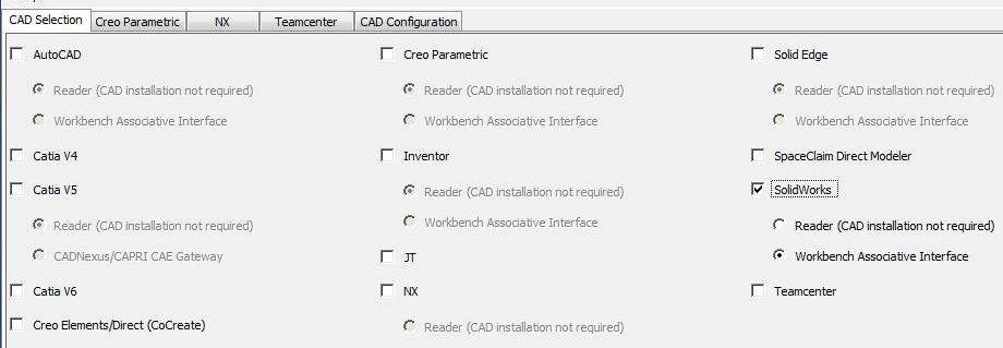
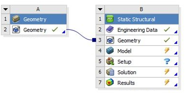
Workbench Meshing
Also known as ANSYS Meshing. The Mesh 'component' in the ANSYS Workbench Toolbox is for CFD meshing and hence Workbench will not link a Mesh component to a Static Structural model. When there are multiple independent geometries to be meshed, it is recommended to follow the method described below.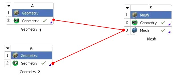
Once 'Geometry' component gets linked to 'Mesh' component, the 'Geometry' tab under 'Mesh' component gets deleted automatically. For cases with interfaces, it is recommended to use 'Mesh' components for each domain separately.
When ANSYS Meshing fails to mesh an edge or a surface, it highlights only that entity. To view the location of failed geometry component, hover the mouse around it to highlight and select neighbouring faces.
Do not use "Update Project" in Workbench unless you want to have 'Solution' performed locally. Update individual components such as 'Mesh' and 'Setup' manually."The mesh translation to Fluent failed due to conflicting zone names." or "Error: Update failed for the Mesh component in Fluid Flow (Fluent)." Fix it with Repair Overlapping Name Selection which is available after right-click on the Named Selections tab.

Utility operations: turn on vertices: Main Menu - Display - Vertex Group - Show Vertices. Sort object names: Use 'Outline' panel above "Model Tree".
Mesh Copy:
Mesh Copy (Tree Outline -> Mesh Object -> Right Click -> Insert -> Mesh Copy) enables copy of a mesh from one body to another. This option helps reduce the mesh setup time for repetitive bodies and parts. Association to CAD is maintained after performing mesh copy. When the mesh is generated, the source anchor body is meshed and the mesh is then copied to target bodies. Bodies which are scoped to a Mesh Copy control are meshed first, and then the remaining bodies are meshed. Prerequisites: The source and target face area should be the same. The associated source and target bodies should have the same volume. The source and target configuration should be identical. Sharp Angle Tool (Mesh Objects -> Insert -> Sharp Angle) controls the capture of features with sharp angles, such as the trailing edge of a blade or the region where a tire meets the road.Creating Virtual Cells
Model Tree -> Right Click -> Insert ->Virtual Topology. Then choose the face (Ctrl+F) or edge (Ctrl+E) selection filter, and then pick faces or edges to be included in the virtual cell(s). To create the Virtual Cell object(s): (a) Choose Merge Cells on the Virtual Topology context toolbar or (b) Virtual Topology object -> Right Click and select Insert -> Virtual Cell or (c) Right click mouse button in the Geometry window and select Insert -> Virtual Cell from the context menu.ANSYS Meshing provides Sweep, MultiZone and Cut-Cell methods to generate full hexa or hexa-dominant meshes. MultiZone method is based on ICEM CFD Blocking approach. One may choose "Source Scoping Method" to 'Manual' when the Program Controlled option does not yield a hexa-dominant mesh. There is an option 'Suppressed' for most mesh controls and default is set to No. If the value is changed to Yes, the mesh control shall has no effect on the mesh (that is, the mesh control features shall get disabled).
Generate Mesh available in Ribbon menu, operates only on active objects that is if bodies or mesh controls are suppressed, they are ignored by the meshing operation. In other words, when there is a combination of suppressed and unsuppressed (active) bodies in a model, the Meshing application meshes only the active bodies. If the model includes multiple parts, they are meshed in parallel. If a size control is applied to a suppressed body, the size control will not affect that body, nor will it influence neighbouring bodies (in general, if a size control is assigned to a suppressed body, that control is also suppressed unless it is also attached to other active bodies).
Sweep Meshing requires topological consistent source and target faces. Only once surface per body can be selected as a source. One need to use Edge Sizing to control the mesh on the source face. This method has option Type which can be set either Number of Divisions or Element Size to specify element size in sweep direction. Sweep meshing is highly influenced by direction of sweep and the source faces need not be coplanar. The left faces of both inner and outer cylinders need to be selected as source faces (including for inflation settings).
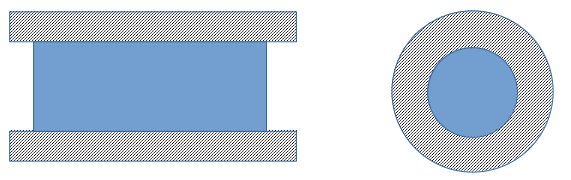
As per ANSYS Meshing user guide, the source and target faces need not have same area and alignment. Though the side faces should be such that they do not break the flow of elements in sweep operation. In other words, the side faces of sweepable body should be mappable. From user guide: "Show Mappable Faces is a good tool to diagnose side faces. All side faces should be mappable, but if they are not found to be mappable, it indicates there may be a problem with the topology." If you select bodies for Sweep operation, the source and target faces would not get selected if these faces are not sweepable (such as multiple segments in a face). "Manual Thin" option in Sweep method is similar to "Thin Volume Meshing" in ANSYS FLUENT.
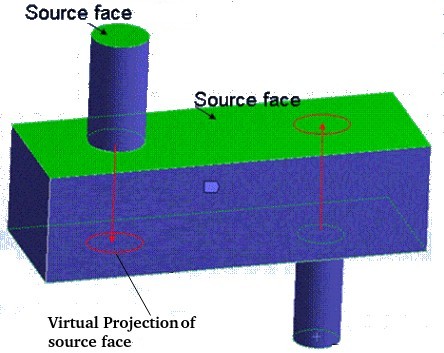
- The general sweeper ignores the Num Cells Across Gap setting used to define proximity-based sizing.
- Hard entities are not supported for the general sweeper.
- If the sweep method is applied to a body and a mapped Face Meshing control is defined for either the source or target face, the sweep mesher shall fail if a mapped mesh cannot be obtained for the face.
- The source and target faces do not have to be flat or parallel. If the topology of the source and target face is the same, the sweeping operation will often succeed even if the shape of the source face is different from the shape of the target face.
- Sweeping does not require bodies to have a constant cross section. However, the best results are obtained for constant or linearly varying cross sections.
- For swept meshes with inflation and match control (periodicity), inflation is performed before the match mesh and sweeping. This can affect the sizing on the match controls, which can in turn lead to meshing failure.
- When sweeping it is only necessary to apply hard divisions to one leg of the sweep path. If the path has multiple edges, apply mesh controls to that path.
- If the sweep path is shared by another body and that path lies on the body's source or target face then more hard divisions may be needed to constrain the sweeper.
Mandatory Requirements of General Sweeper
- The side faces of the sweep must all be sub-mappable and must have single loops.
- The source face cannot be a closed analytic such as a full cylinder, torus or sphere. However, partial analytics are acceptable as source and target faces.
- body cannot be swept if there is a completely contained internal void in the body.
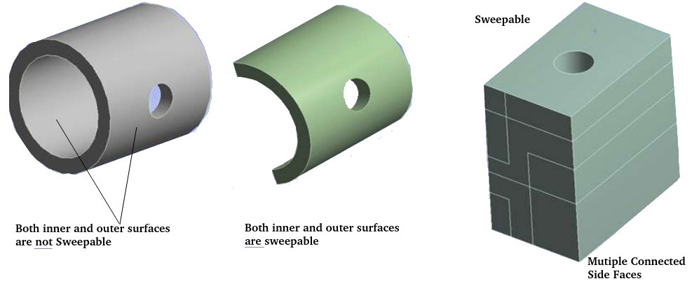
Features of Thin Model Sweeping
- It does not require a topologically matching source and target. The model may have multiple source and/or target surfaces.
- The model must be thin, that is when virtually unfolded, thickness or dimension in one direction << dimensions in other two directions.
- The source(s) and target(s) cannot touch each other.
- The model must have an obvious "side" that is nearly perpendicular (or sharp angle with no smooth connection) to the source and target where all of the side faces directly connect from source to target.
- Mesh controls defined on the target may not be respected.
- Multibody parts are supported. For multi-body parts, only one division through the thickness is possible.
- For single body parts, multiple elements through the thickness using the Sweep Num Divs control can be defined.
- The features vertices, edges, and faces on the target may not be preserved.
- Bodies with triangular cross-section such as blades with zero trailing edge radius and smooth connection at leading edge do not meet thin sweep meshing criteria.
- No edges or vertices are allowed on side faces that is side edges must connect directly from source to target.
Example of splitting geometry to make a body sweepable
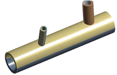
Meshing Object -> Advanced -> Use MultiZone for Sweepable Bodies: If set to On, the mesher uses the MultiZone method instead of General Sweeping for sweepable bodies. The default setting is Off.
Selective Meshing refers to the method to manually picking (Right Click and use option to mesh selected body) the bodies and meshing them incrementally (sequentially). There is no explicit option named Selective Meshing similar to MultiZone or Sweep option available in a drop-down. The successive mesh operation shall use the attached face meshes. The mesh quality and size depends on the order in which bodies are meshed. Mesh Object -> Advanced -> Allows/disallows selective meshing. The default value is Yes.
Using selective meshing, after meshing a body manually, one can mesh the whole part or assembly or continue meshing individual bodies. To generate mesh in the remaining bodies of the model, use the Generate Mesh feature from ribbon tab. From user's guide: "Using selective meshing, you can selectively pick bodies and mesh them incrementally. After meshing a body, you can mesh the entire part or assembly or continue meshing individual bodies. To generate the rest of the mesh in the model, use the Generate Mesh feature."Selective meshing is not conducive to a geometry update or re-mesh operation. Use the Mesh worksheet (Mesh Object -> Right Click -> Start recording) to create a selective meshing history so that meshing steps can be repeated automatically in the desired sequence. Otherwise, body meshing steps need to be repeated manually if the single mesh update does not meet meshing requirements.
Hard or Soft Behaviour option for (edge or face) sizing is available only if "Capture Proximity" and "Capture Curvature" options are set to No. Only if a 'face' is defined by two "edge loops", the the "Internal Number of Division" field is available. The left face is 'sweepable' section whereas the right faces is not sweepable.
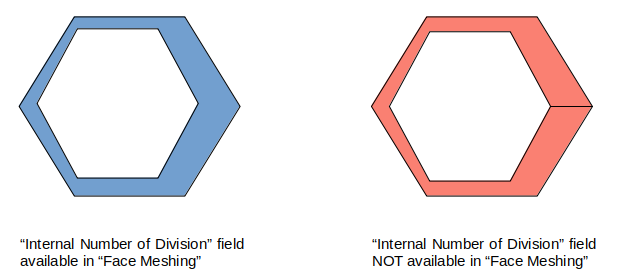
Assembly Meshing
Workbench meshing provides two types of meshing algorithms under Assembly Meshing: Cut-Cell and Tetrahedrons. As per user guide: "CutCell Cartesian meshing is a general purpose meshing method designed for Ansys Fluent. The Tetrahedrons assembly meshing algorithm is a derivative of the CutCell algorithm, with strengths and weaknesses similar to those of CutCell. The Tetrahedrons method starts from the CutCell mesh and through various mesh manipulations creates a high quality unstructured tet mesh."MultiZone Meshing
To determine whether the MultiZone mesh method is an appropriate method for a geometry and to ensure blocking is constructed properly, consider the following characteristics of the problem: (1) Sources (2) Sweep paths (the side faces) and (3) Intersections (levels). To classify a MultiZone problem, consider which faces will be sources and in turn, which sources will cause imprinting. All faces that are not sources are the side faces, and make up the sweep direction. From the user guide:- Select both source and target faces. MultiZone internally decides which faces to take as sources and which to take as targets.
- To do imprinting of face loops, all swept section faces (that is, those that are perpendicular to the sweep direction) should be selected.
- Source faces will generally be meshed with a free mesh. Depending on the geometry, mapped face meshing controls can be added to these faces to get mapped meshing.
- Using Virtual Topology to Handle Fillets in MultiZone Problems: The presence of fillets in a model can cause problems for MultiZone, since arguably a fillet could be either a side face or a source face and the mesh quality in the corner could be problematic. Ideally, a fillet should be split in half, with one half going to the source face and the other half going to the side face.
- In MultiZone, size controls are first applied on the edges.
Hex-Dominant Meshing:
The Hex Dominant method creates free (unstructured) hex dominant mesh and is recommended for bodies that cannot be swept. This method is most useful for "meshing bodies with large amounts of interior volume" and "meshing bodies that transition from sweepable bodies in a body that has been decomposed for sweeping". This method is not suitable for thin complicated bodies where mesh count may increase compared to a tetrahedron mesh since the element size must be much smaller to create well shaped hexahedrons. Mesh Matching for cyclic symmetry is not supported for hex dominant meshing.Hex-dominant does not apply proximity sizing defined under "Mesh Object".Cartesian Meshing in ANSYS Meshing:
When Cartesian meshing is selected under Method, all bodies in the model are automatically selected. This indicates that Cartesian meshing cannot be part of "Selective Meshing".Meshing in TurboGrid
- .tse session files are produced by TurboGrid and contain CCL commands
- .tst state files are produced by TurboGrid and contain CCL commands
- .tgt topology files are produced by TurboGrid and define the topology
- .tginit is TurboGrid initialization file
- .gtm mesh files are produced by TurboGrid and contain the mesh in a format which can be read by Ansys CFX
- .inf information files contains machine data (rotation axis, number of blade sets, length unit), names of geometry definition curve files for the hub, shroud, and blades, leading and trailing edge settings
- Machine data required for the generation of passage of a fluid domain needs to be provided before loading the curve files
- .crv and .curve files are used by TurboGrid to define machine geometry, these files contain points in free-format ASCII style
- How is the shape of periodic Boundary defined? Periodic boundary generally follow the twist of the blade. GAan option called "Bias of Blade towards High-Periodic" is normally set to 0.5, which means centered between the periodic boundaries.
Mesh Formats
In its simplest form, a mesh is a collection of list describing coordinates of nodes and its connectivity with neighbouring nodes. Additionally, it may contain material information, name of a zone or domain a node and element belong to.
NASTRAN format
NASTRAN format is commonly known as *.bdf format where BDF stands for Bulk Data Format.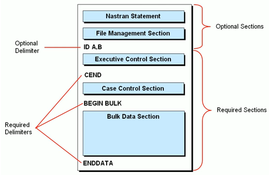
- The first two sections, NASTRAN statements and File management section are optional and they can end with the optional delimiter "ID A, B"
- Comments start with $ character
- Each line contains 80 characters and can span over multiple lines. The continuation entry at the end of a line start with + and same entry appears on the next line.
- Executive control section ends with the mandatory delimiter "CEND"
- Case control section ends with the mandatory delimiter "BEGIN BULK"
- Bulk data section ends with the mandatory delimiter "ENDDATA". Geometry model, mesh connectivities, finite element properties, materials, restrictions and loads are described in this section.
- The Bulk data section is composed of entries where each entry contains data distributed in fields.
- Each line has has 10 fields of width 8 characters each. That is each field is 8 column wide. The entry name is given in the first field of the first line.
- Tenth field on each line indicates whether there is an additional line in the entry or not.
- NASTRAN uses three different formats for data in an entry:
- Free Field Format: data fields are separated by commas or spaces. To skip a field, two commas in succession are used. Itegers or string with > 8 characters causes FATAL error.
- Small Field Format: there are 10 contiguous fields, each of them is 8 characters long
- Large Field Format: there are 10 contiguous fields, each of them is 16 characters long and hence spreads over two lines of 80 characters each. Asterisk * symbol after the keyword is added to indicate this format.
- The node coordinates are defined in the Bulk data section, in the entry named GRID. EID: Element Identification Number, PID: Propertey Identification Number, Gi: Grid Point Identification number of connection points.
- Elements are designated as CTRIA3, CTRIA6, CQUAD4, CQUAD8, CTETRA, CPENTA and CHEXA.
ANSYS format
The content of ANSYS structural *.ans file is as follows:- Section-1: it contains basic information about the way solve has to run. All the lines starting with 'COM' are comments. e.g.
/BATCH
/PREP7
/COM NODE DEFINITIONS
- Section-2: this section contains the node definition starting with a statement for coordinate system e.g. CSYS,0. each statement starts with the keyword 'N'.
N,10,2.3,-1.7,-13.75
N,11,1.7,-3.0,-13.75
N,12,0.0,2.3,-13.75
N,13,0.5,1.6,-13.75
N,14,1.0,1.0,-13.75
- Section-3: the material properties are defined in this section.
/COM Material properties
EX,   1,  2.068000E+08
NUXY, 1,  2.900000E-01
DENS, 1,  7.820000E-06
GXY,  1,  8.015504E+07
ALPX, 1,  1.170000E-05
KXX,  1,  4.500000E+04
- Section-4: real constant table, element type and element coordinate system is defined in this section.
R,1,,,,,,
ET,    1,  45,   0,   0,   0,   0,   0,   0
TYPE,  1 $ REAL, 1 $ MAT,1
ESYS,  0
- Section-5: here each statement starts with keyword 'EN' followed by element numbers and nodes defining that element.
EN,10,29,31,53,45,30,32,54,46
EN,11,20,24,23,19,45,53,51,43
EN,12,45,53,51,43,46,54,52,44
EN,13,19,23,22,21,43,51,49,47
EN,14,43,51,49,47,44,52,50,48
EN,15,21,22,9,8,47,49,27,25
- Section-6: this section contains boundary condition (reaction points, loads and supports), analysis type (static, harmonic, transient ...)
CSYS,0
/SOLUTION
ANTYPE,0
/COM NODAL DISPLACEMENT RESTRAINTS
D,1850,UX,0.,,,,UY,UZ,ROTX,ROTY,ROTZ
/COM FACE PRESSURE LOADS
SFCUM,PRES,ADD,1,1
...
SFE,  1496, 1,  PRES, 0,  1.00000
SFE,  1497, 1,  PRES, 0,  1.00000
SFE,  1498, 1,  PRES, 0,  1.00000
SFE,  1499, 1,  PRES, 0,  1.00000
...
KBC,0
TIME,  1.0000
AUTOTS,OFF
NSUBST,  1
...
OUTPR,NSOL  ,1
OUTPR,RSOL  ,1
OUTPR,ESOL  ,1
OUTPR,NLOAD ,1
OUTPR,VENG  ,1
...
SOLVE
FINISH
OpenFOAM format: The mesh in OpenFOAM is stored in a 'polyMesh' directory in 5 different files as described below:
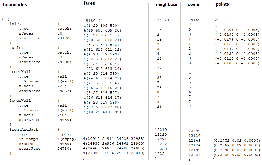
- boundary: name of boundary patches, the startFace is the index into the face list of the first face in the patch and nFaces is the number of faces in the patch.
- face: element numbers inside the boundary patches. In the case of boundaries, the connected cell is the 'owner' and the 'neighbour' is assigned the label '-1'.
- neighbour: a list of neighbour cell labels. Each face is therefore assigned an 'owner' cell and 'neighbour' cell so that the connectivity across a given face can be described by the owner and neighbour cell labels.
- owner: a list of owner cell labels, the index of entry relating directly to the index of the face, so that the first entry in the list is the owner label for face 0, the second entry is the owner label for face 1 ... The 'owner' file contains an entry for nCells which defines how many cells are in their domain.
- nodes: node number and X, Y, Z coordinate
Example of mesh for a square block
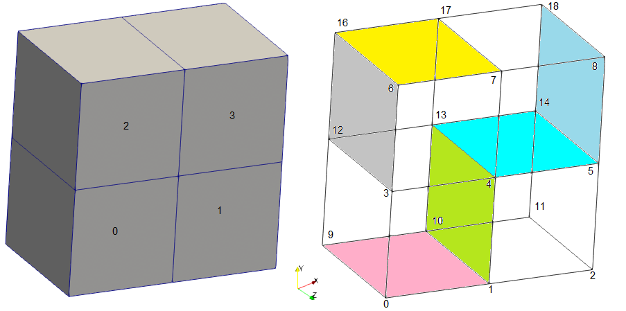
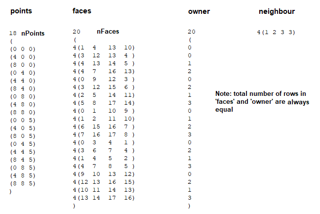
Example of 2D mesh shown below can be located here. This file can be opened in ParaView by selecting "All File (*)" for "File of Type" field. Select "FLUENT Case Reader" when prompted. ParaView shall give following warnings - clic Apply to open the mesh.
Warning: In C:\bbd\ecd3383f\ build\ superbuild\ paraview\src\ VTK\IO\ Geometry\ vtkFLUENTReader.cxx, line 423 vtkFLUENTReader (0000021A2224D7E0): Unable to open dat file.
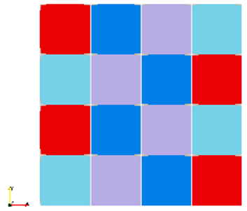
Example of 3D mesh shown below can be located here.
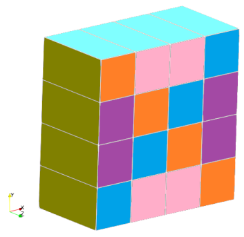
Here are the ANSYS Input File and Abaqus Data File for the geometry / mesh described above.
- Node:
(10 (zone-id first-index last-index type ND)(
x1 y1 z1
x2 y2 z2
.
.
xn yn zn
))
If 'zone-id' = 0, it provides the total number of nodes in the grid. In such a case: 'first-index' = 1, 'last-index' = total number of nodes in hexadecimal, 'type' is meaningless, 'ND' = dimensionality of the grid. There will be no X-, Y-, Z-coordinates following the statement and the parentheses for the coordinates will be omitted. For example, (10 (0 1 2bd 99 2)). Note hexadecimal system has base value of 16 (analogous to base value of 10 in decimal system) and digits 0, 1, 2, 3, 4, 5, 6, 7, 8, 9, A, B, C, D, E, F. In decimal systems 358 = 3x10x10 + 5x10 + 8. In hexadecimal system, 2bd = 2x16x16 + 11x16 + 13 = 701. In MS-Excel HEX2DEC function can be used to convert a hexadecimal number into any other base. e.g. HEX2DEC("2bd") = 701. Note, hexadecimal number is represented as string even though it represents a number, due to presence of text character. - Periodic Shadow Faces: 18
- Cells: 12
element-type description nodes/cell faces/cell 0 mixed - - 1 triangular 3 3 2 tetrahedral 4 4 3 quadrilateral 4 4 4 hexahedral 8 6 5 pyramid 5 5 6 wedge 6 5 - Faces: 13
- interior: 2
- wall: 3
- pressure-inlet, inlet-vent, intake-fan: 4
- pressure-outlet, exhaust-fan, outlet-vent: 5
- symmetry: 7
- periodic-shadow: 8
- pressure-far-field: 9
- velocity-inlet: 10
- periodic: 12
- fan, porous-jump, radiator: 14
- mass-flow-inlet: 20
- interface: 24
- parent (hanging node): 31
- outflow: 36
- axis: 37
- Face Tree: 59
- Cell Tree: 58
- Interface Face Parents: 61
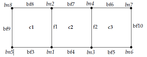
(0 "Grid:")
(0 "Dimensions:")
(2 2)
(12 (0 1 3 0)   )
(13 (0 1 a 0)   )
(10 (0 1 8 0 2) )
(12 (7 1 3 1 3) )
(13 (2 1 2 2 2) (
1 2 1 2
3 4 2 3))
(13 (3 3 5 3 2) (
5 1 1 0
1 3 2 0
3 6 3 0))
(13 (4 6 8 3 2) (
7 4 3 0
4 2 2 0
2 8 1 0))
(13 (5 9 9 a 2) (
8 5 1 0))
(13 (6 a a 24 2)(
6 7 3 0))
(10 (1 1 8 1 2) (
1.0000e+00 0.0000e+00
1.0000e+00 1.0000e+00
2.0000e+00 0.0000e+00
2.0000e+00 1.0000e+00
0.0000e+00 0.0000e+00
3.0000e+00 0.0000e+00
3.0000e+00 1.0000e+00
0.0000e+00 1.0000e+00))
Definition of zones: cell and face zones
Face Zones: This section describes the connectivity of faces (i.e. which points are connected to form a face), the type of faces (i.e. interior or exterior) as well as the volumes in which such faces are belong to. The section begins with the header (0 "Faces:"). The next line (13 (0 1 1a 0)) gives information for the total number of faces used in the domain. In this line, '1' stands for the first index of faces and '1a' for the last index. Thus, the total number of faces in this particular domain is '1a' i.e. 1 x 16 + 10 = 26. The header '13' refers to faces, '0' at the end stands for boundary.(0 "Faces:") This is a Header
(13 (0 1 1a 0)) ➔ (13: stands for faces (0, 1: First index of faces, 1a: last index of faces, 0))
(13 (3 1 a  3 0) (
  3 2 6 4 5 0
)
(13 stands for faces (3: wall-boundary faces, 1: first index of boundary faces, a: last index of boundary faces, 3, 0))
(3: number of points consisting a face, 2: the first point index, 6: the second point index, 4: the third point index, 5: first volume that face belongs to, 0: second volume index, 0 stands for boundary)
(13 (5 b 1a 2 0)(
  2 4 b 1 2
)
(13 stands for faces ( 5: interior faces, b: first index of interior faces, 1a: last index of interior faces, 2, 0))
(2: number of points consist a face, 4: the first point index, b: the second point index, 1: the first volume, 2: second volume)
The Cells Section: (0 "Cells:")
In this section, the total number of cells of the domain are given. The following lines are seen:(0 "Cells:") (12 (0 3 c 0)) (12 (2 5 c 1 2))The first line is a header. In the second line: 12: stands for cells, 3: First Index of Volumes, c: Second Index of Volumes
(0 "Zones:") Header
(45 (2 fluid air)()) ➔ (45 stands for boundary conditions or interior (2: interior, fluid:fluid or solid: in this example 'fluid', fluid: the name is air))
(45 (3 wall front)()) ➔ (45 stands for boundary conditions or interior (3: wall, wall: the name is 'front'))
(45 (5 interior default-interior)()) ➔ (45 stands for zones (5 is interior and describes the volumes)
(0 "Zone Sections")
(39 (11 fluid FLUID)())
(39 (12 interior int_GEOM)())
(39 (13 interface INTERFACE_A1)())
(39 (14 interface INTERFACE_A2)())
(39 (15 velocity-inlet INLET)())
(39 (16 wall WALL_BLWR_CASING)())
(39 (17 outlet-vent OUTLET)())
STAR-CCM+ format - cell topology identifier for STAR-CD CCM format is described below. The format *.sim used by latest version of STAR-CCM+ from Siemens is proprietary and no description is available in public domain.
- 1: Point (FLUENT: 10)
- 3: STAR_LINE_CELL, 21 STAR_QUADRATIC_EDGE
- 3: Shell
- 4: Shell with midside vertices
- 11: Hexahedron
- 12: Prism
- 13: Tetrahedron
- 14: Pyramid
- 21: Hexahedron with midside vertices
- 22: Prism with midside vertices
- 23: Tetrahedron with midside vertices
- 24: Pyramid with midside vertices
- 28: Line with 1 extra node
- 29: Line with 2 extra nodes
- 255: Polyhedron
- One Dimensional: 3 STAR_LINE_CELL, 21 STAR_QUADRATIC_EDGE
- Two Dimensional: 5 STAR_TRI_CELL, 7 STAR_POLYGON_CELL, 9 STAR_QUAD_CELL. 22 STAR_QUADRATIC_TRIANGLE, 23 STAR_QUADRATIC_QUAD
- Three Dimensional: 10 STAR_TET_CELL, 12 STAR_HEX_CELL
COMSOL format: The mesh file format contains a section with mesh points coordinates, followed by sections with mesh element information, divided into separate subsections for each mesh element type. A COMSOL mesh contains elements for all space dimension levels. For example, a tetrahedral mesh consists of domain (tetrahedra), boundary (triangles), edge, and vertex elements. Furthermore, each element has an index to the geometric entity it belongs to. If a mesh file is incomplete—for example, if it only contains tetrahedrons - the "Mesh Import" operation automatically generates the missing element data.
STL format
This format describes only the surface geometry of a 3D object without any representation of color, texture or attributes. It is primarily a 3D mesh format and has limited or no use in 2D. STL is a unit less format. FreeCAD works internally in millimetres, it exports 1 mm = 1 unit.It encodes the mesh information using a simple concept called 'tessellation'. The quality of STL mesh is controlled by Chord Height or Chord Tolerance and Angular Deviation or Angular Tolerance.
Angular tolerance: this the angle between the normals of adjacent triangles. Decreasing the tolerance (which can range to 0 to 1) improves feature capturing.
Chord height: it is the maximum distance from the surface of the original design and the STL mesh. A smaller value improves the facet representation of the actual surfaces.
solid part0
 facet normal n1 n2 n3
  outer loop
   vertex x1 y1 z1
   vertex x2 y2 z2
   vertex x3 y3 z3
  endloop
 endfacet
 facet normal ...
 ...
endsolid part0

solid part1
...
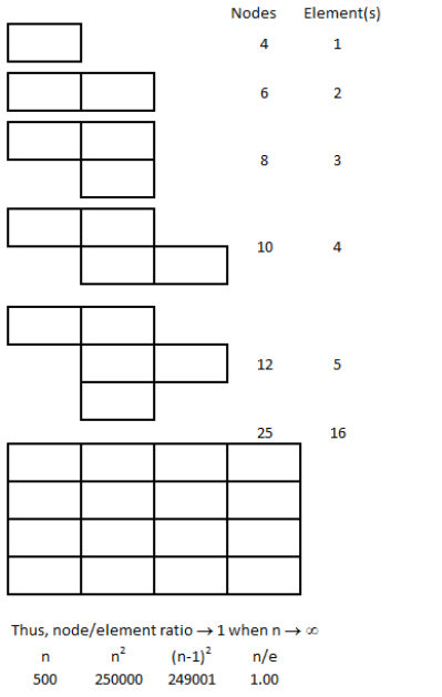
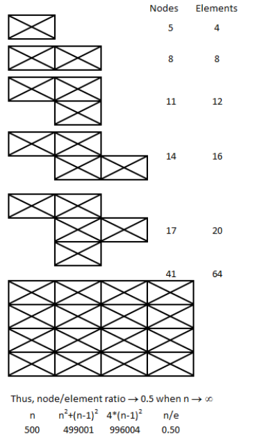
Morphing
Reference - Multi resolution Mesh Morphing by Aaron W. F. Lee et al.: Metamorphosis (or morphing) is the process of gradually changing a source object through intermediate objects into a target object. It has numerous applications from modelling to the generation of animation sequences for the movie and advertising industries.Blender Tool for Geometry Clean-up
Blender is not a CAD modeling program. For example, there is no concept of solids even if it is enclosed from all sides by faces, the concept of Boolean (add, subtract...) in Blender is not same as standard 3D CAD tools. Note that you can extrude a face and the operation is named as Solidify. Since Blender works on tessellated geometries, they are 'hollow' or "empty inside" by definition. The attributes such as mass or matter inside an object, centre of gravity... cannot be assigned to objects in Blender. 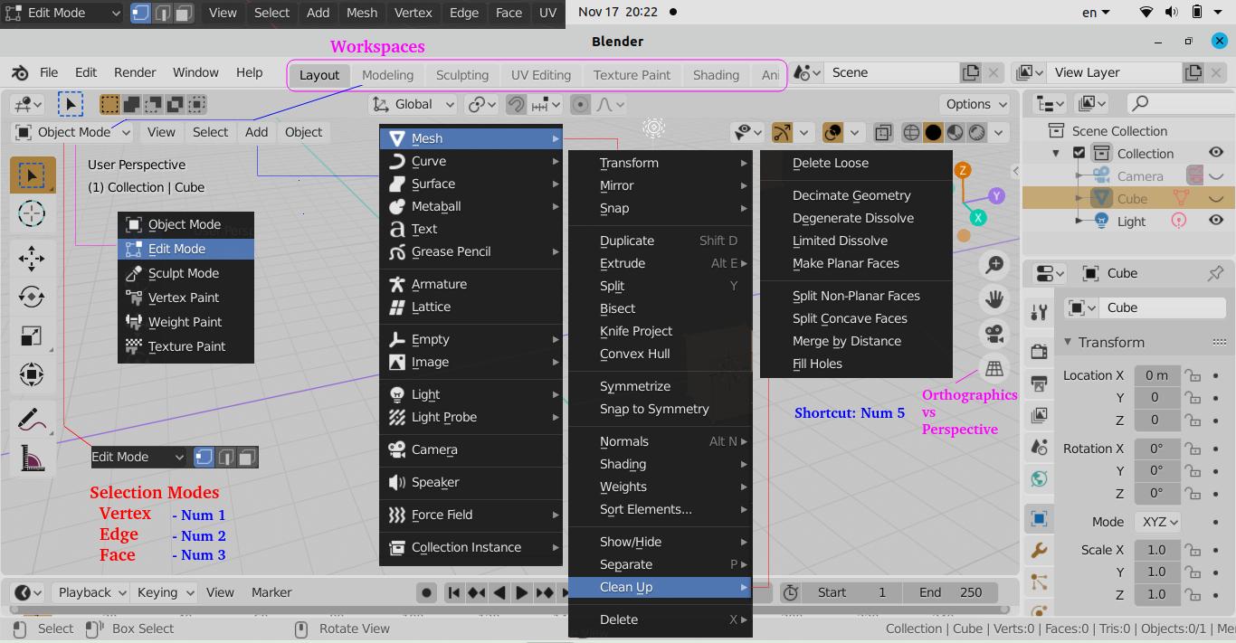
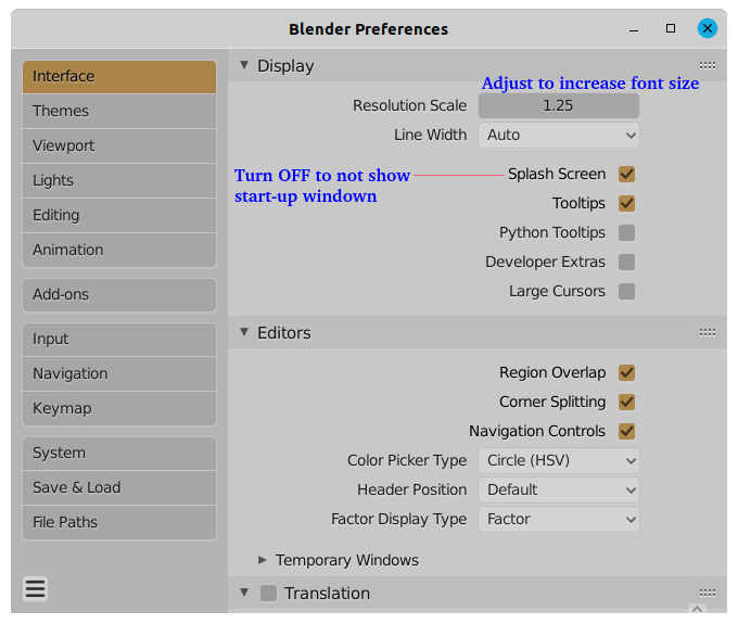
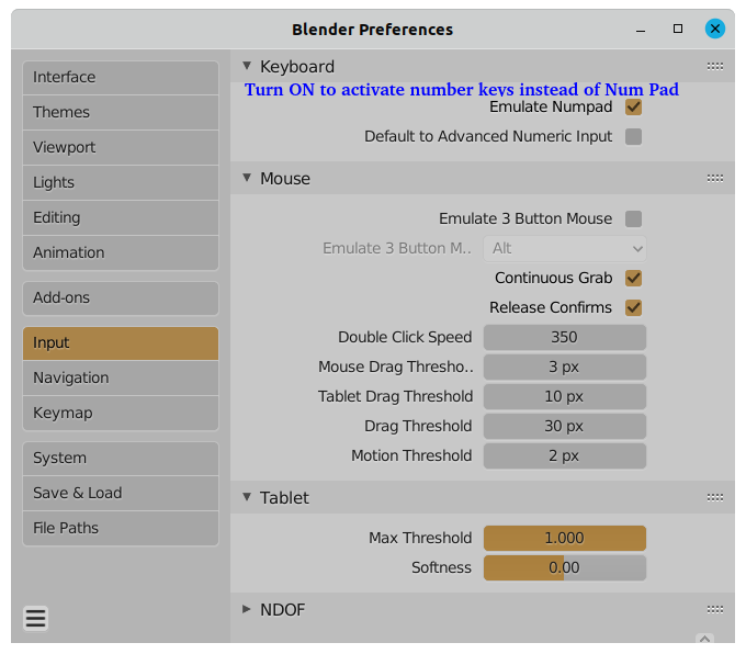
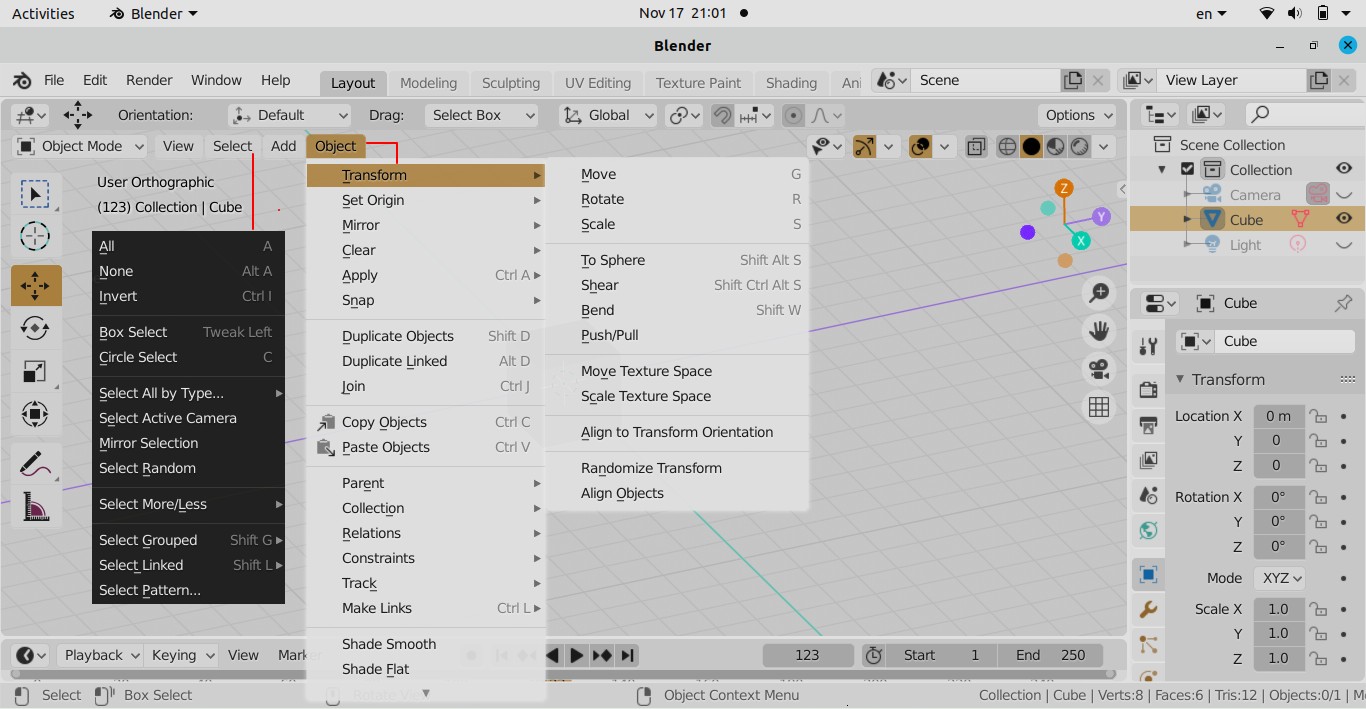
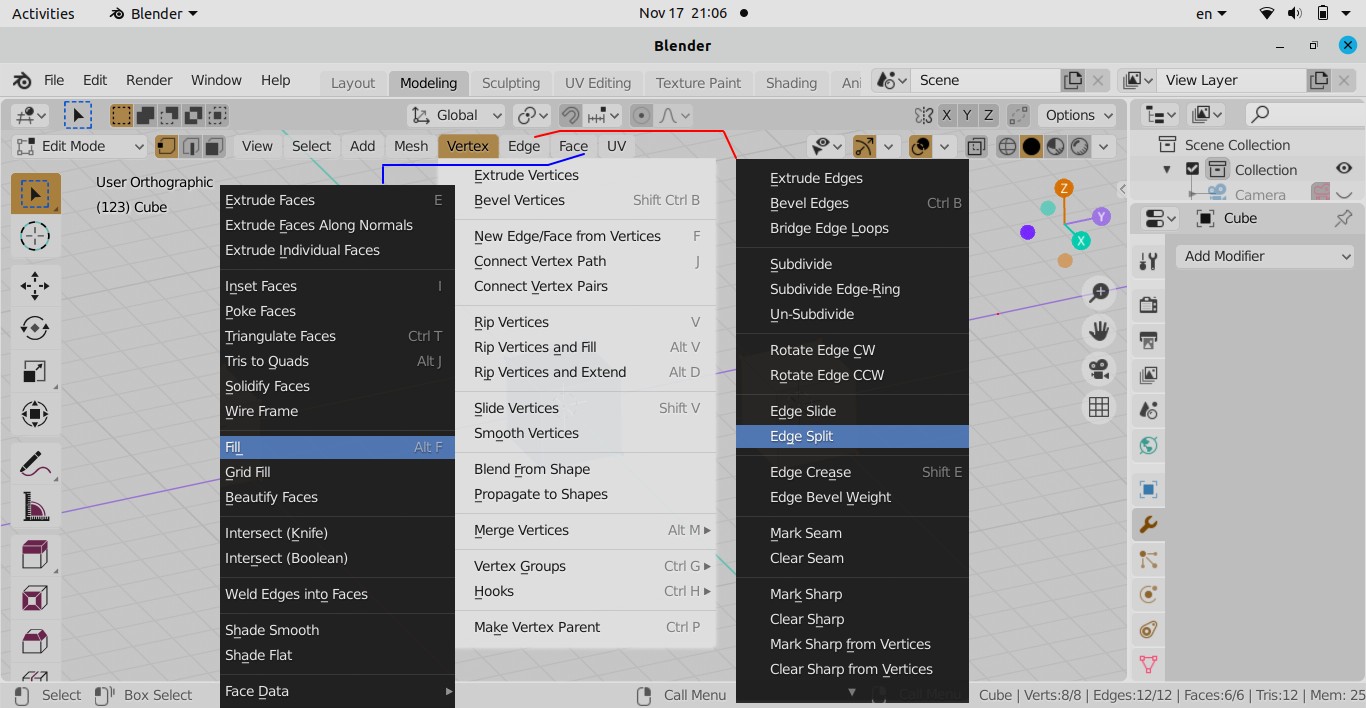
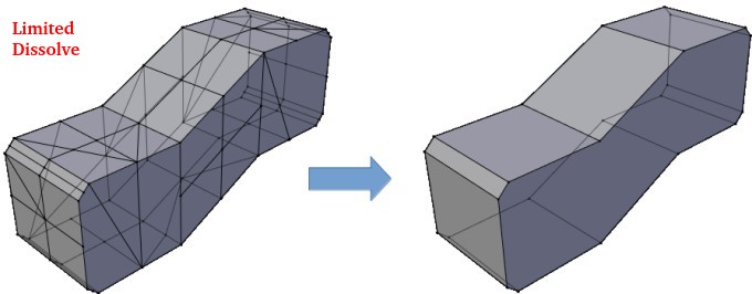
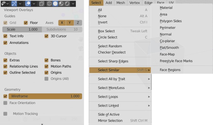
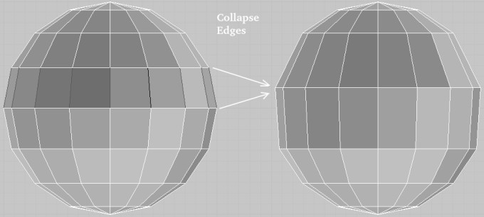
Fix for Viewport Clipping
Also known as object cut-off issue, zooming in to inspect texture or mesh details in 3D view clips faces partially like a clipping mask not showing the full model. Click on the small left arrow (< sign) on the top right near XYZ-triad to open the following pane. 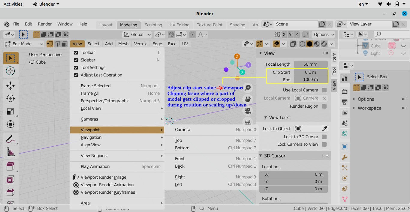
The content on CFDyna.com is being constantly refined and improvised with on-the-job experience, testing, and training. Examples might be simplified to improve insight into the physics and basic understanding. Linked pages, articles, references, and examples are constantly reviewed to reduce errors, but we cannot warrant full correctness of all content.
Template by OS Templates