- CFD, Fluid Flow, FEA, Heat/Mass Transfer: FEEDBACKS/QUERIES - FB@CFDYNA.COM
BOUNDARY CONDITIONS
ICEM CFD for Mesh Generation
Features and Capabilities of ICEM CFD
ICEM CFD was a feature rich tool in its time. After takeover by ANSYS, the development has nearly stopped and only diehard fans tend to use it. Otherwise, it is an excellent tool that require some enhancement to improve (poor) geometry import capabilities.

ICEM CFD has a feature called "Blocking". This is used to generate high quality structured hexahedral mesh where user can control the mesh size, mesh growth ratio and edge biasing. While using blocking technique, following tips may help:
- Move the blocks to appropriate part as you go no spliting. Do not wait till all desired spliting operations are complete.
- Check quality after pre-mesh. One need not display the mesh after every pre-mesh operation. At the same time, the pre-mesh quality histogram shall get updated every time mesh is recomputed.
- Many a time the poor mesh or negative determinant is due to wrong project of edges/surfaces. This may happen when a block is moved to new part and neighbouring block(s) are left in some other domain. The edge may get projected to the nearest surface which otherwise should have remained an internal edge.
ICEM CFD MESHING FAQ: |
|
[Q] I have created mesh in two separate project using blocking technique?
I am unable to merge the two set of data? [A] Ansys Recommended solution is described in this hyperlink. |
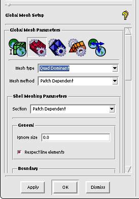
| [Q] I am using patch-dependent surface meshing in ICEM and the mesh quality on individual surface is good. However, the line elements the the common edge of two surfaces are overlapping though the number of elements on that edge is set to be same!
[A] Check and toggle on the checkbox "Respect Line Elements" under Global Mesh Setup --> Surface Mesh.
|
| [Q] I have created a cross-section of axi-symmetric model using points,
curves and arcs. However, ICEM CFD is unable to create a surface from lines. Even,
"Close Hole" option under "Repair Geometry" tab failed!
[A] There are two ways to resolve this issue:
|
| [Q] I have written a long script to create a very complex 2D domain using
bottom-up approach. The naming convention used for points is pnt1, pnt2, ..., pnt10,
pnt11, ... Some temporary points required to create an arc are center points named as cp.
However, the script is generating a point named cp00. When I checked the script, there is
no name "cp00" appearing in it.
[A] This might have happen when you would have tried to create a point named "cp" second time without deleting the first one. As per default setting, ICEM does not allow to overwrite an entity name. |
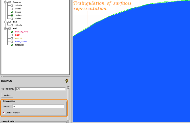
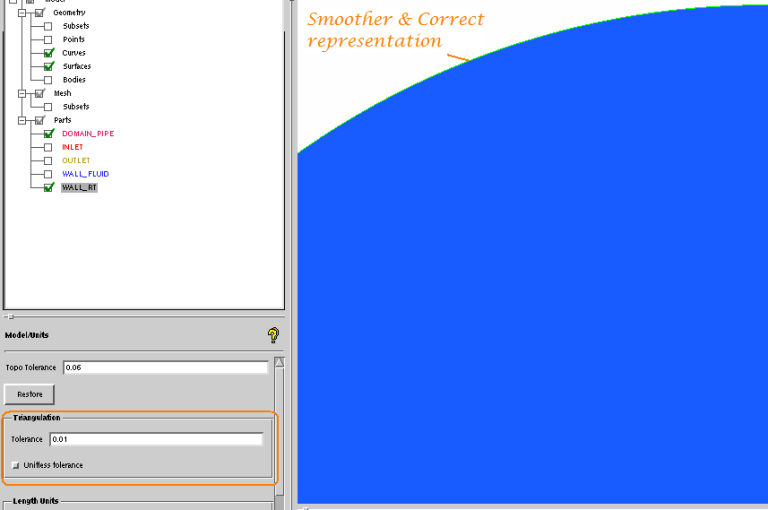
| [Q] The surfaces in ICEM do not look very smooth. Also, when I extracted an Iso-line, it does
not seem to lie in the plane of the surface. Is it an aberration or just a visualization issue? [A] This is a program setting issue. All the surfaces in CAD environment are represented as what is called Tessellation. Set the triangulation tolerance to an appropriate low value. Read the user manual about "triangulation toleration" and its effect on treatment of geometry in ICEM. See the effect of this tolerance as demonstrated below!
|
| [Q] ICEM is not dividing a particular curve as per the number of nodes set explicitly. The mesh is being generated by "Patch-dependent" method.
[A] Check the global mesh setting parameter. Is natural sizing on? What value MIN mesh size to ignore set to? Though mesh sizing on curve takes priority over Global setting, natural sizing is also meant for curves. Hence, check which of the two is the smallest one? The element size after setting number of nodes should be greater than the value set in Global Mesh Sizing Option. |
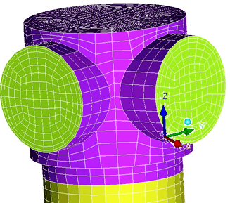
| [Q] I have many T-junction in my geometry. How can I generate good quality HEXA mesh.
[A] Using the blocking technique in ICEM CFD and O-grid split, a high quality mesh can be generated for any tye of T-junction or Y-junction. Refer to few examples below. 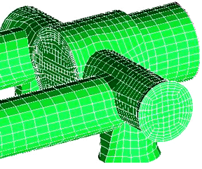
|
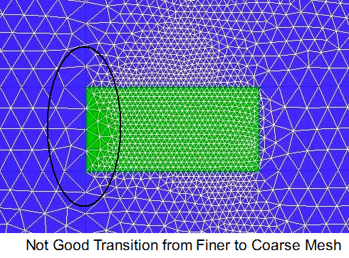
| [Q] The transition from a fine mesh to coarse mesh is not consistent and as desired.
[A] A good transition from a fine mesh to coarse mesh requires consistent meshing set-up for all the geometrical entities: points, curves and surfaces. It is advised to keep the lines and points in the parts defining the finer mesh and set meshing parameters using parts option instead of individually on every line and surface (unless there is some specific requirements). The mesh with not correct transition is shown below. The left curve defining the boundary of smaller patch was kept in the part encircling the patch. 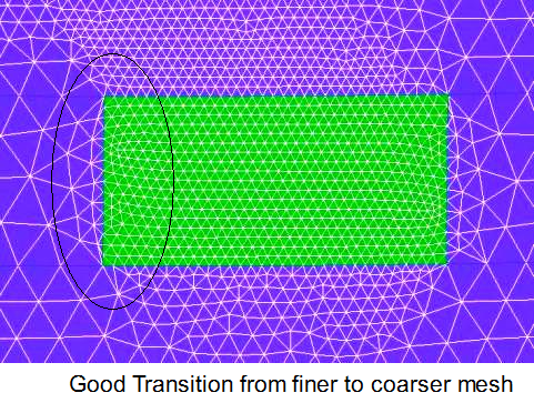
|
| [Q] Fluent automatically assigns interface to zones which are supposed to be interior.
[A] If a part is named with prefix INTERFACE such as INTEFACE_ABC and then exported as fluent format. When it is imported in Fluent (read mesh operation), fluent will automatically assign it the zone type 'interface'. In order to change it to zone type 'interior', first convert it to zone type 'wall' and then to 'interior'. However, once and interface or wall is set to interior, it cannot be directly set to zone type interface using the drop down option (as this option will not be available). The zone type back to interface now be set through 'TUI' only.
|
The content on CFDyna.com is being constantly refined and improvised with on-the-job experience, testing and training. Examples might be simplified to improve insight into the physics and basic understanding. Linked pages, articles, references and examples are constantly reviewed to reduce errors, but we cannot warrant full correctness of all content.
Copyright © 2017 - All Rights Reserved - CFDyna.com
Template by OS Templates